Category Archives: Transmisions/final drives

Post #70: Report on the New Weapons Board

Post #70: Report on the New Weapons Board

I downloaded this PDF, Report on The New Weapons Board 1944,  someplace, but since I don’t remember where I hosted it too.  The report documents the feedback the troops gave to the board on the various weapons they demonstrated.

The report was put together in early 44 to document feedback from the troops on current weapons, and proposed improvements, and replacements. There is a good amount of information on the M4 medium tank, and US Armor in general. Most of the combat feedback comes from the fighting in Italy, and North Africa.

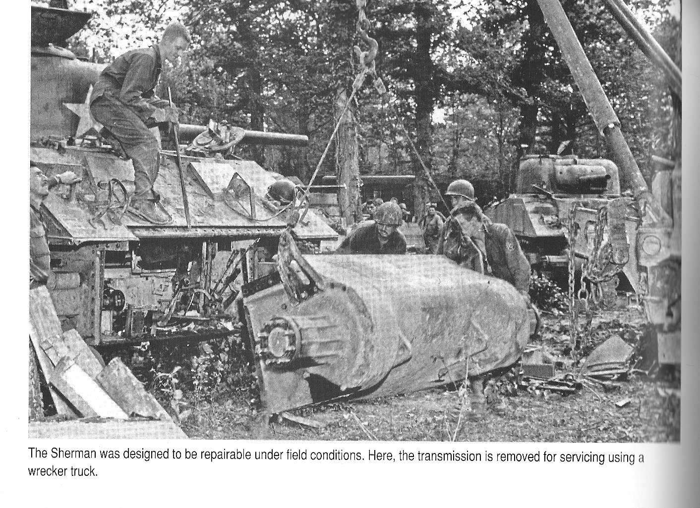
The report also sheds an interesting light and gives evidence for the view that the US Army didn’t consider the improved early Sherman bad, and only wanted it replaced with something much better.  It also gives some interesting insight into the Shermans and what condition they were in when they got to the using units.

Feedback on current equipment and changes.

This is a typical M4 Sherman in Italy, the battalion is being used as an artillery battery, and this is an early production M4 with the M34 gun mount and it probably has a three-piece differential as well. It may even have DV ports. These tanks were common in the MTO even into 1944.

The first thing is this to note about the Sherman is the first mention of it is praise for the current models. This quote stands out, “No new type is desired unless the improvement in military characteristics is sufficient to warrant the changes and defects in the present standard tanks are avoided.” 

Another early model M4 in Italy, cheek armor, M34 gun mount, and an early 3 piece differential.

They did have a list of improvements they did want either done to the Sherman and to make sure the follow-on model, the T20 series incorporated them. 

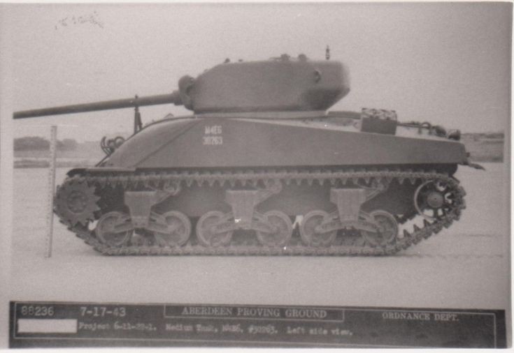
  1. They wanted a 76mm gun like the 3-inch gun on the M10.  The news of the 76mm M1 series and the new Shermans mounting the gun interested the troops a lot. They brought an M4E6 76mm Sherman to show to the troops.
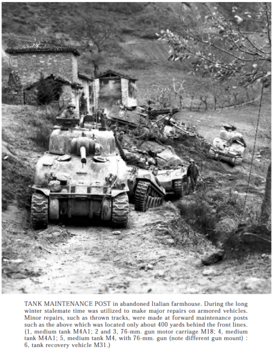
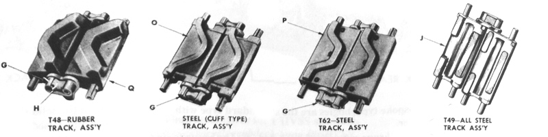
  2. Improved suspension and tracks. It turns out the rubber block tracks with no chevron were not well liked and wore out very quick in rocky, hilly terrain. The steel chevron blocks with rubber backs were well like and lasted much longer. This feedback is mostly from the MTO, the mountainous and rocky landscape was hard on tanks and even the Sherman had some issues. The complaints about the suspension had more to do with width than durability.
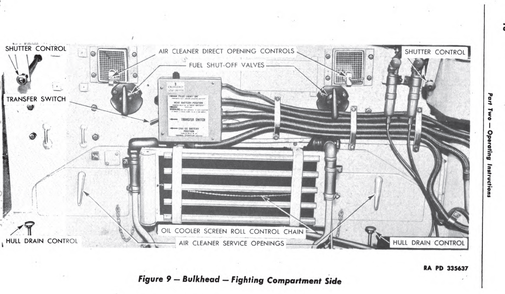
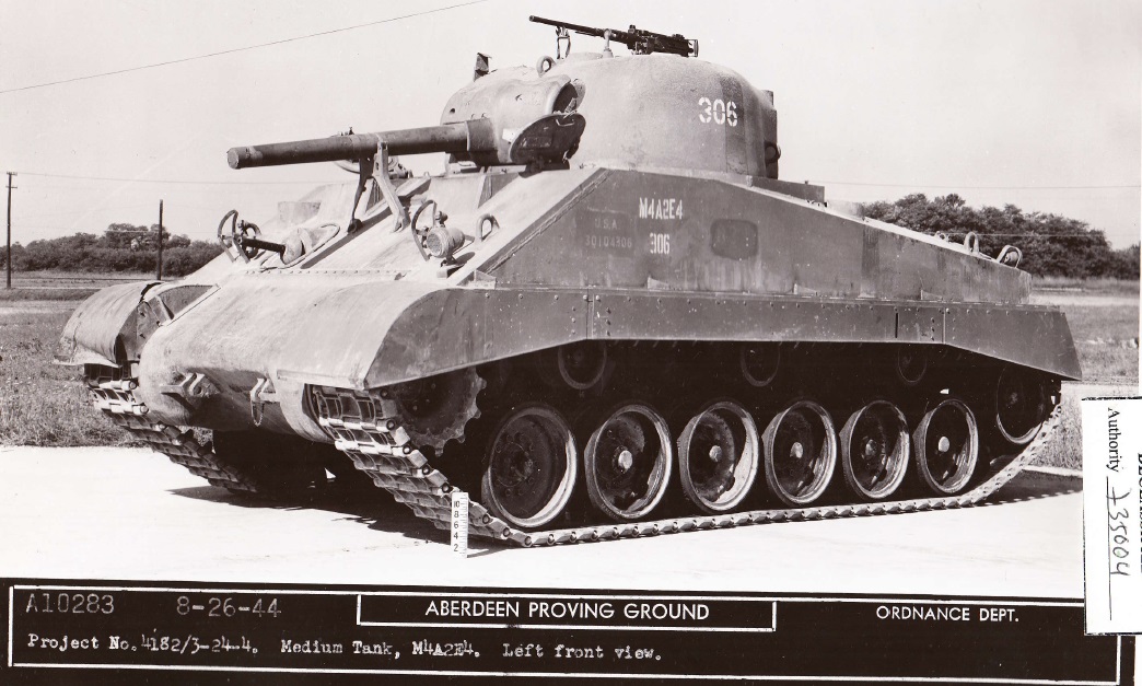
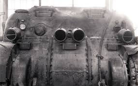
  3.   They wanted armored air cleaners on the M4 and M4A1 tanks.  It turns out the Air cleaners mounted under the overhang on the rear hull of the M4 and M4A1 tanks were prone to damage, and this damage was not expected and didn’t pick up until Italy so there was a shortage. All other models had the air cleaners inside the hull. Some units added improvised armor and some were added later in the production runs.
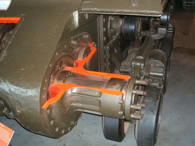
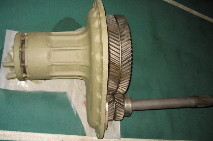
  4. Better ballistic angle around the front of the transmission housing.  The old three-part differential is what they are talking about. Most early Shermans had this type, and the armor was thinner than the later cast single piece units. There were two cast versions, an early thinner, but still no worse than the three-piece unit, and a later improved thicker one. There was a demand for add-on armor over this area, but it was never approved.
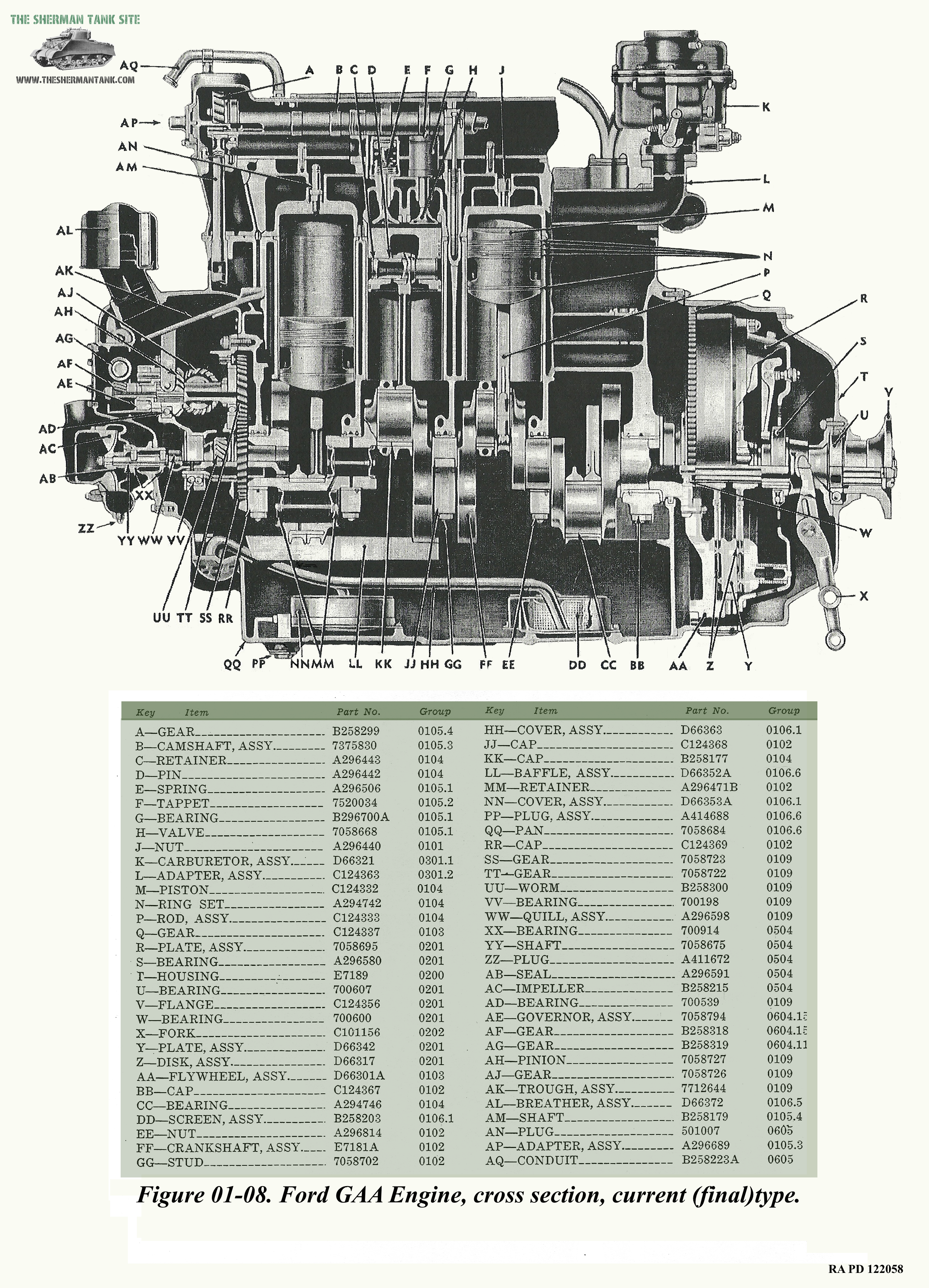
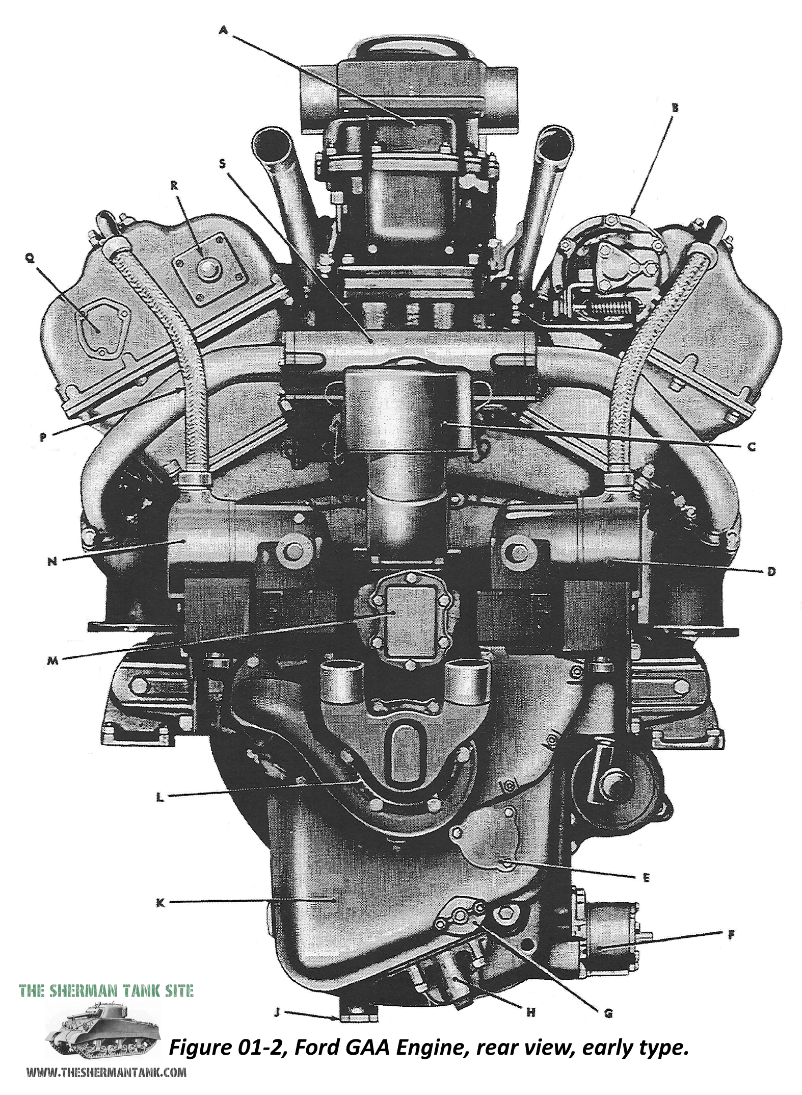
  5.  More power. Yet, when the M4A3 Ford GAA powered Shermans came online, they did not want to swap them in as replacements, and only wanted whole units who trained on them stateside first to be issued the improved tanks.  The M4A4 and M4A2 were not big enough improvements to switch to those motors. 
  6. Diesel engine. The US Army rejected the GM 6046, claiming it was not as reliable as the R975, but all the nations that did use this motor liked it.
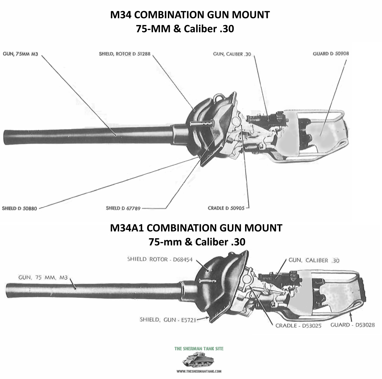
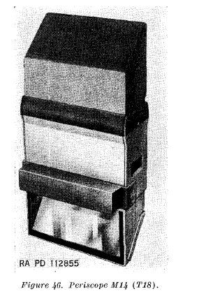
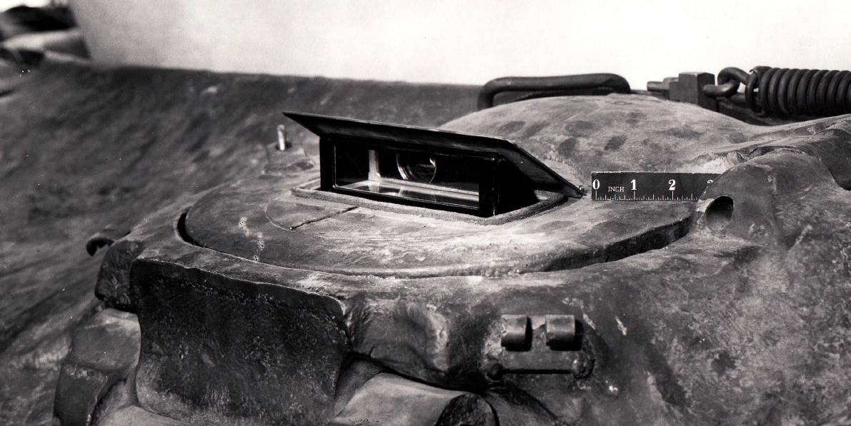
  7.  They wanted better sights and fire control equipment. Many tanks in the MTO and NATO(North African Theater of Operation) had not gotten the M34A1 gun mounts with telescopic sights. The mount for the periscope sight had not seen major improvements, though there were field mods to make it work. The using arm was enthusiastic about the changes in the second gen Shermans fire control, but wanted even more advanced features, like rangefinders, and improved telescopes, since the current ones shot loose too!

There is also other tank related info.

  • The M3 75mm Gun –  Though well-liked for infantry support and deemed to be reliable and durable, the using arms almost universally felt the German 75mm PAK 40 guns were much better anti-tank weapons, and a high-velocity 76mm gun was in demand.
  • 75mm ammunition – these fixed rounds came unfixed, sometimes even in their travel packaging.  They wanted this fixed. They wanted the WP shells ballistics to match the ballistics of the common HE shell.
  • Large caliber cartridge cases – Steel cases for the 75mm rounds for the M3 gun were well received and proved more durable.  This was not the case for 105mm howitzer rounds.
  • 105mm howitzer armed tanks – This was not a popular notion because the M7 105mm GMC was inaccurate when used for direct fire to support infantry assaults.  The new weapons board did not agree, and plans for this vehicle were already in motion, and it would be well liked once issued.
  • Tank Officers – they wanted a tanker officer in the high-level headquarters to advise Division and higher level officers the best way to use tanks. AA and Tank destroyer officers were already an accepted part of these HQ staffs.
  • the 17-pdr gun – There was more interest in using this gun in M10s since the install was much simpler, the Sherman install was complicated and cramped and the Army was leary.
  • Tank Tracks – They show up again and the plain rubber block tracks could wear out in 250 miles in rocky terrain and lacked good off-road traction, and the using arm felt they were only good for training on roads.  The T54E1 steel chevron type was preferred and much more durable, but the T48 rubber chevron would work in the MTO but wore out faster than steel types. The T49 bar cleat was also not good on sidehill terrain. The using arm wanted a wider center guided track in the MTO because the side guided tracks on the Sherman were prone to throwing on irregular and rocky side slopes. Extended end connectors were well received by the using arms.
  • Tank Suspension – Sherman suspension was found to be durable, with few volute springs failing. The biggest problem was the bogie wheels since the rubber tires had an erratic failure rate, and unlike the spring failures, usually sidelined the tank.
  • Ammunition stowage – They using arms were not interested in changes that reduced the number of ready rounds. The turret ready racks were very popular and crews did not like their removal with the ‘quick fix’ mods. They were willing to risk the higher fire chance, for the faster rate of fire the early storage setup allowed. The crews did not get their way on this one, at least until the M26 went into production.
  • The Radios – They wanted a better radio in the M32 recovery vehicles and better, more comfortable headphones for the armor crews.
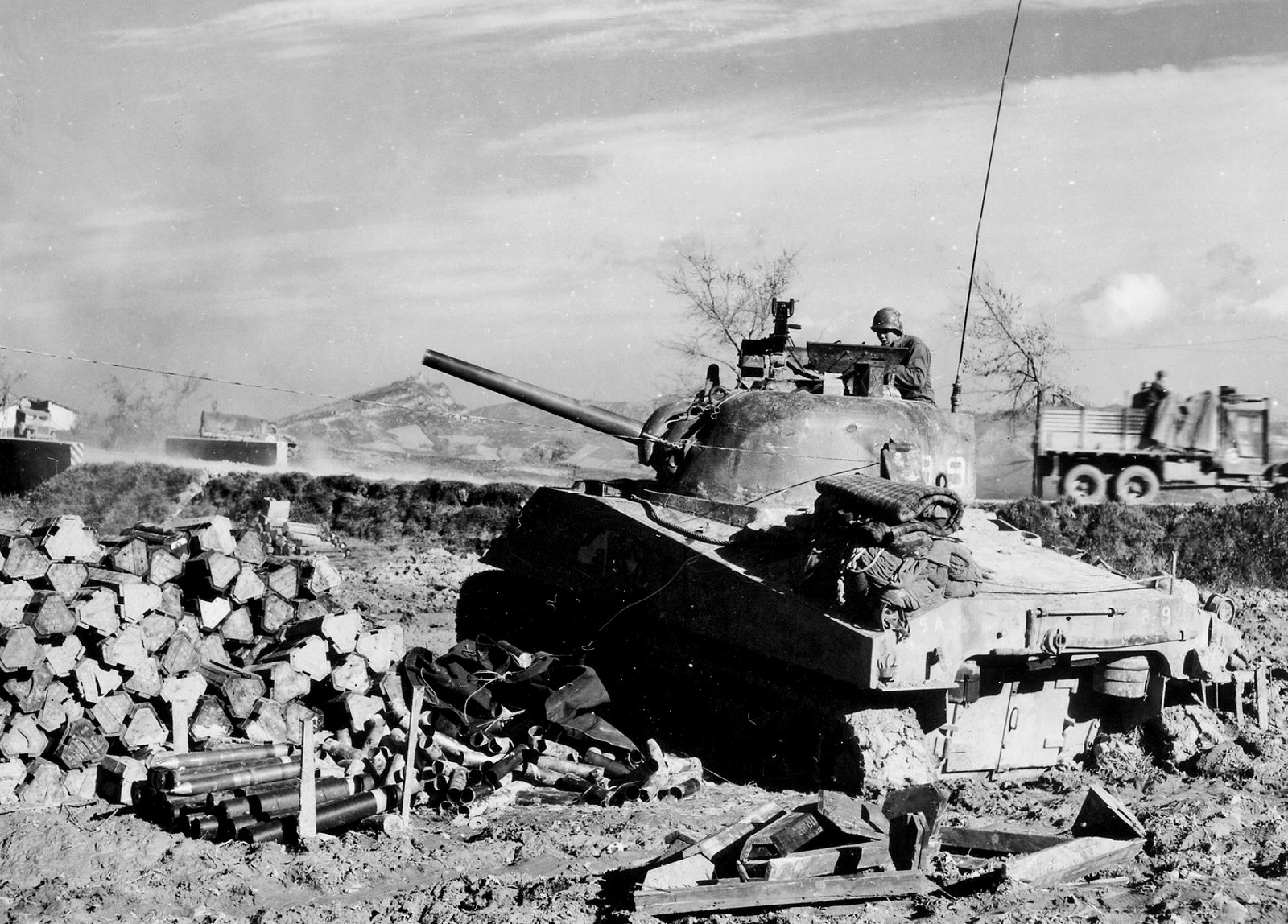
  • The M10 GMC – This TD was very popular, and received high praise all around. The using arm did not require a replacement, just improved M10s. ♠ One thing to note, most M10 GMCs in MTO lacked the Azimuth indicator and range quadrant. Since the M10s get used as artillery a lot in the MTO, they would like replacements to have them.
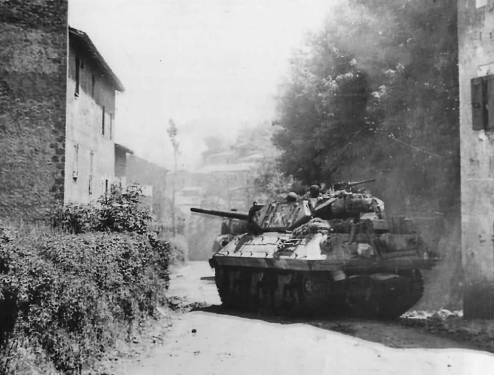
    M10 in Italy.
  • Replacement gun tubes – The using arms were very annoyed, that all type of gun barrels from machine gun and mortar, to tank and artillery, were dispensed at a very miserly rate.  The using arm argued replacement barrels should be bought at the rate that took into consideration how much ammunition for the same weapon was produced.
  • Improved fire control for all relevant vehicles –  They wanted built-in rangefinders, or portable ones supplied. Better periscope and telescope sights and all vehicles that could be used for indirect fire to receive the full suite of tools to perform the task.   I had never heard that some Shermans did not get these automatically. I’m not sure why some Shermans and TDs didn’t have the Azimuth indicator M19 and elevation quadrant M9. Maybe the crews dumped them to save space, maybe the tanks were rushed and built and approved without them I’ll try and find out. They mention 75% of the tanks in England had these items, but less 50% had them in the MTO.  Tank units were much more commonly used for indirect fire in the MTO than they would be in the ETO.
  • Engines –  The R975C-1 was getting around 200 hours before needing replacement. 
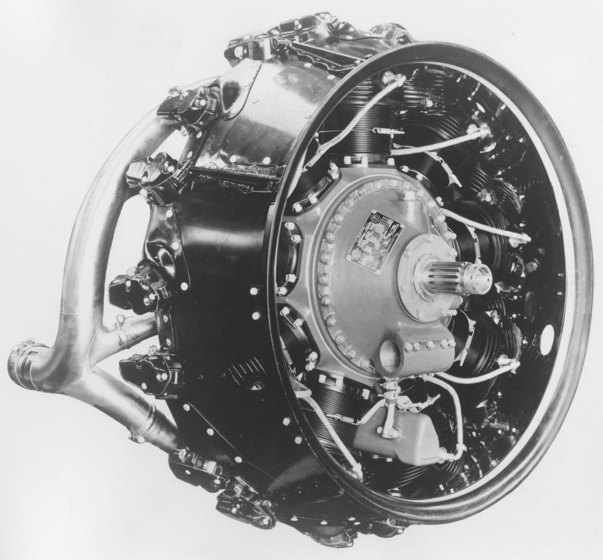
This was fine with the using arm, though they would like 60 to 100 more horsepower.  The R975 needed little maintenance to reach the expected 200 hours and many run much longer.  The lack of liquid cooling system has some advantages.
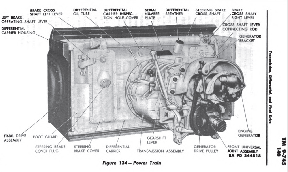
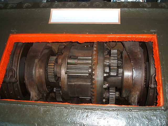
  • Powertrain –  There was a higher than expected rate of clutch failure in the desert campaigns. The clutch system was also improved on the production like with improved leverage to lower the clutch pedal pressure. Many MTO units did not receive the improved clutches or linkages.  The better clutches lead to better transmission life and better shifting, and even without the improved clutches, transmission life went up in Italy.  The powertrain offered excellent service and generally outlived the engines by several overhauls if not damaged.
  • Crew comfort – the Driver and Co-drivers seats in the Sherman were found to be ok, but higher seat backs were requested along with deeper seat cushions. The Gunners seat was found to be ok but could use the same improvements as the driver’s seats but the Command and Loaders seats were deemed all but useless. These would be improved in the later models of the Sherman and various TDs.  Crews do not use their seatbelts, fearing it complicating bailing out, and more padding inside was not wanted because the crews felt it was a fire hazard.  The M4 and M4A1 tanks were praised for good ventilation. There was also some discussion about the value of turret baskets, and if they were needed at all.
  • Ammo Storage – The early Sherman ready racks in the turret were well liked by the using arms, but they felt the sponson and hull ammo racks were no good and didn’t support the 75mm Shells enough. They would often separate and dump a bunch of gunpowder inside the tank making a deadly mess to clean.  The using arm tends to stuff the tank with extra rounds, adding to the shell durability problems. These problems would be addressed in the second gen improved hull tanks.
  • General storage – The current storage space on the Sherman was deemed ok, but better, easier to access bins were requested. They also wanted any storage in the floor to be resistant to getting filled with dirt or water.
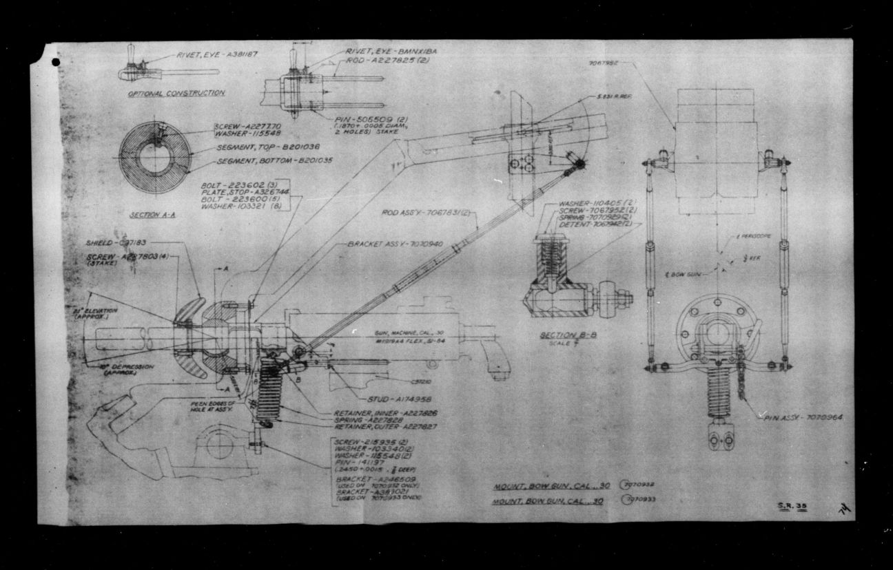
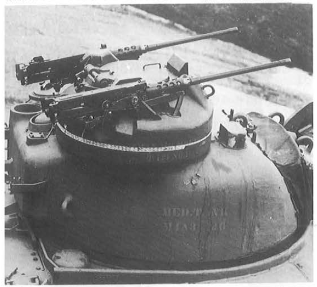
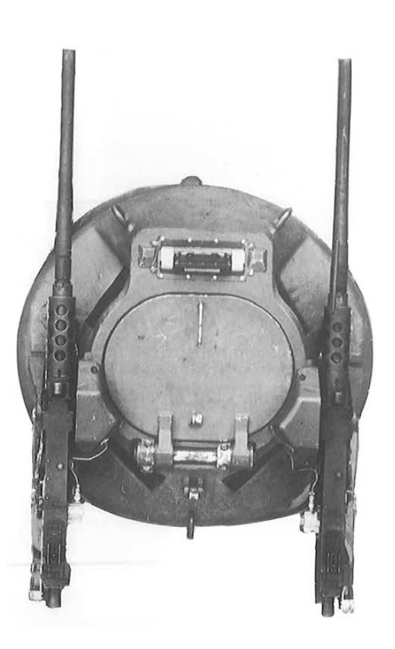
  • Machine guns – The bow machine gun saw a lot of use, but its usefulness would be improved by a sighting system. One was in the works, but not at the point of this report.  The M1919 machine guns, both bow, and co-ax were reliable as long as the crew was careful with the ammo. Long road trips could vibrate rounds loose in the belts and cause problems, but under normal conditions, this was rarely a problem with well-trained crews.  The crews wanted a better adjustment method for matching the co-ax gun to the gunner’s site, the current one was not very good.  The .50 AA mount was not well liked or considered important. Requests were made for a better mount for ground targets.
  • Turret hatches – The current split hatch was deemed ok, but the crews like the looks of the new all around cupola and were also enthusiastic about a loader’s hatch on the new 76 armed tanks.
  • Armor – There does not seem to be a consensus on how much armor a tank should have by the using arms.  Armored Force troops felt the current level on the Sherman was fine, but wouldn’t mind more as long as it did not negatively affect flotation, maneuverability, and speed. ♠The British generally wanted heavier armor than the US Army.    ♠♠Combat in Italy showed the differential was taking more hits than anything, and another request was made for add-on armor for the area.
  • Sand Shields – The general consensus on these was they were useless in any theatre and needed to be redesigned. They needed to be easier to install, and designed to not trap mud.
  • Flotation – The using arms wanting tanks around 10 pounds per square inch. This was very optimistic since even the HVSS Shermans came in around 11 PSI, the basic 75 VVSS Sherman around 13.  It seems the Germans flooded fields in Sicily and Italy when they retreated, and Shermans got bogged down most of the time.  They offered the suggestion of just stretching the Sherman since more length would help, and the British M4A4 tanks, the longest production Shermans, had no maneuverability issues.
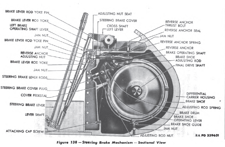
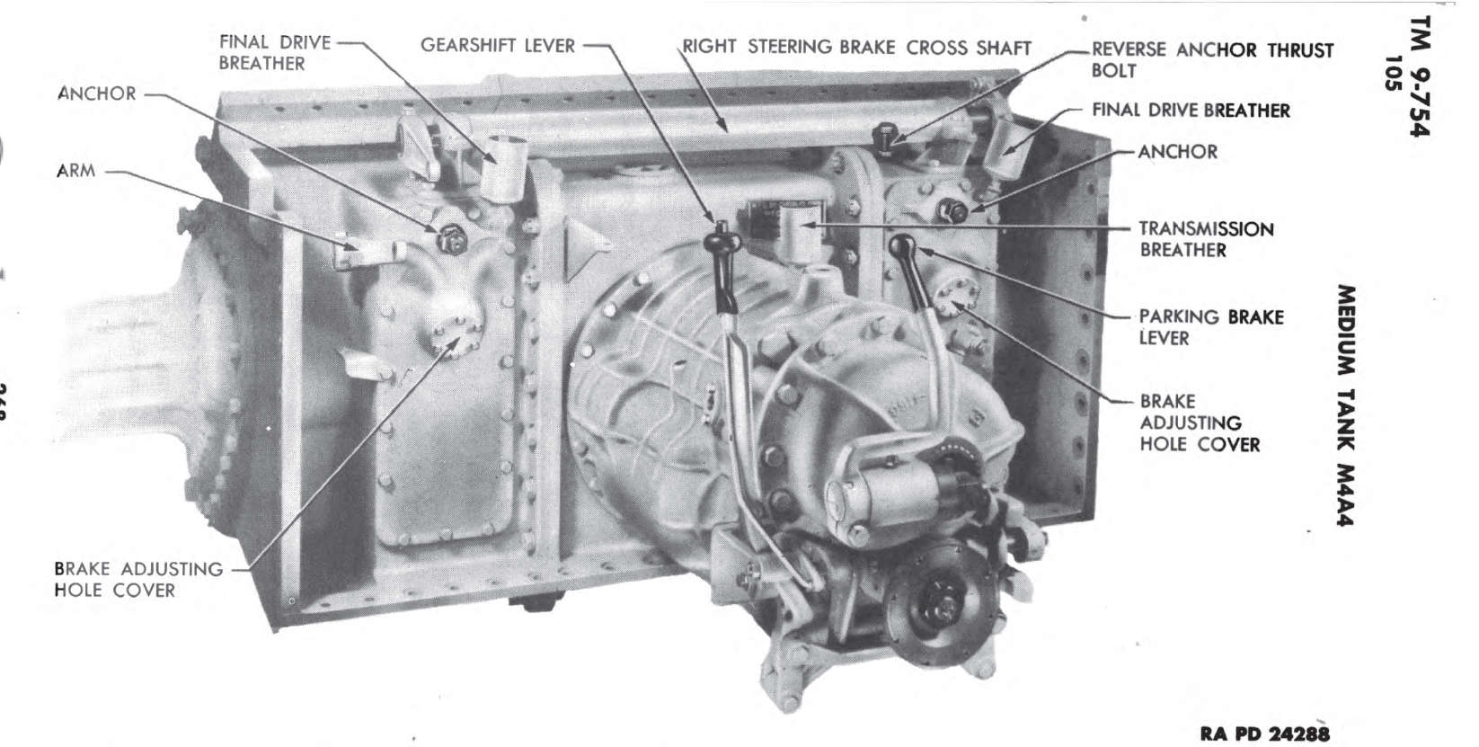
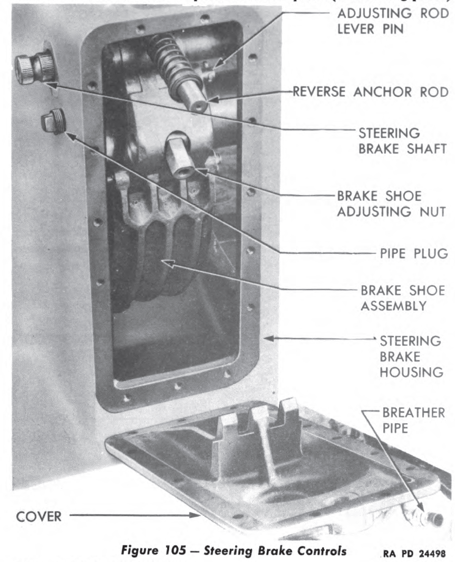
  • Maneuverability –   In the US Army there was a desire across the board for more maneuverability, in tanks. One thing to keep in mind though is the tanks in the MTO were older and most had single anchor steering brakes, the double anchor made the tanks easier to maneuver requiring less lever pressure. The ability to skid turn was not something US troops seemed interested in.
  • Accessories – The troops had a lot of feedback here. ♠ The instruments and gauges in medium tanks were not good quality, if they worked they didn’t work long. Oil pressure gauges fail, and no one worries about the motor until both oil pressure gauges die and a low oil pressure light comes on. This seems to be US feedback, I don’t recall hearing complaints from the Brits about Gauge quality. I wonder if the different tank plants sourced gauges from different companies. ♠♠ The compasses on US tanks would not stay calibrated. This would be a very annoying problem but eventually solved on second gen Shermans. ♠♠♠ Armor for the air cleaners on the M4 and M4A1 comes up again. ♠♠♠♠ The Auxiliary giving good service, and are well liked, but the using arms would like the area around the fuel tank filler for the Aux motor to be waterproofed better.  They also noted replacements were hard to come by.
  • Modifications –  ♠ The jist on this one was, in many cases modifications can be seen by inspecting a vehicle, but in others, access panels or more might have to be removed to check. The using arms proposed a record imprinted on a brass plate, attached to the vehicle, listing all the modifications that had been applied. ♠♠ They also wanted to emphasize that they did not want any modifications that would not ‘materially increase  the efficiency of the vehicles’
  • Development – The using arms were curious about the items in development, and finding out a large organization was working to improve almost everything was a morale booster. There was also interest in the T-20 series and if any test vehicles would be sent over for some for feedback like the M4A1 prototype has been.


Information and feedback on future equipment. 

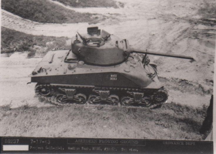
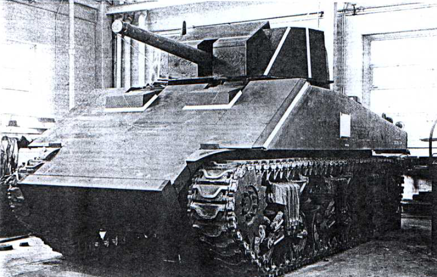
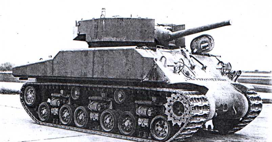
  • The M4E6 or pre-production M4A1 76w –  ♠ This improved version was well liked by everyone who checked it out. The bigger turret was a big hit, though not much bigger, it seemed roomier. ♠♠ The improved fire control gear was very well liked and considered an ‘outstanding improvement’.  The 76mm gun was well liked, and everyone seemed to agree needed. ♠♠♠ The only real concern was the less effective HE round, but it was hoped they would make a better one.
  • The M18 76mm GMC –  The first and bad impression this vehicle lefts was it had no armor, and seemed very mechanically complicated.  The fire control gear was well liked. When the vehicle was demonstrated, the tracks and unthrowable tracks also got a lot of attention.  No one was sure if the speed would be useful, but the maneuverability was well liked. ♠ The same story with interest in deployment, not as a replacement vehicle, but fulling trained units from the ZI would be ok. ♠♠ This vehicle was not wanted by M10 units already deployed. Units equipped with it in the ZI then deployed were better received, the M10 was still more popular.  An M10 with a 90mm gun was the preferred replacement.
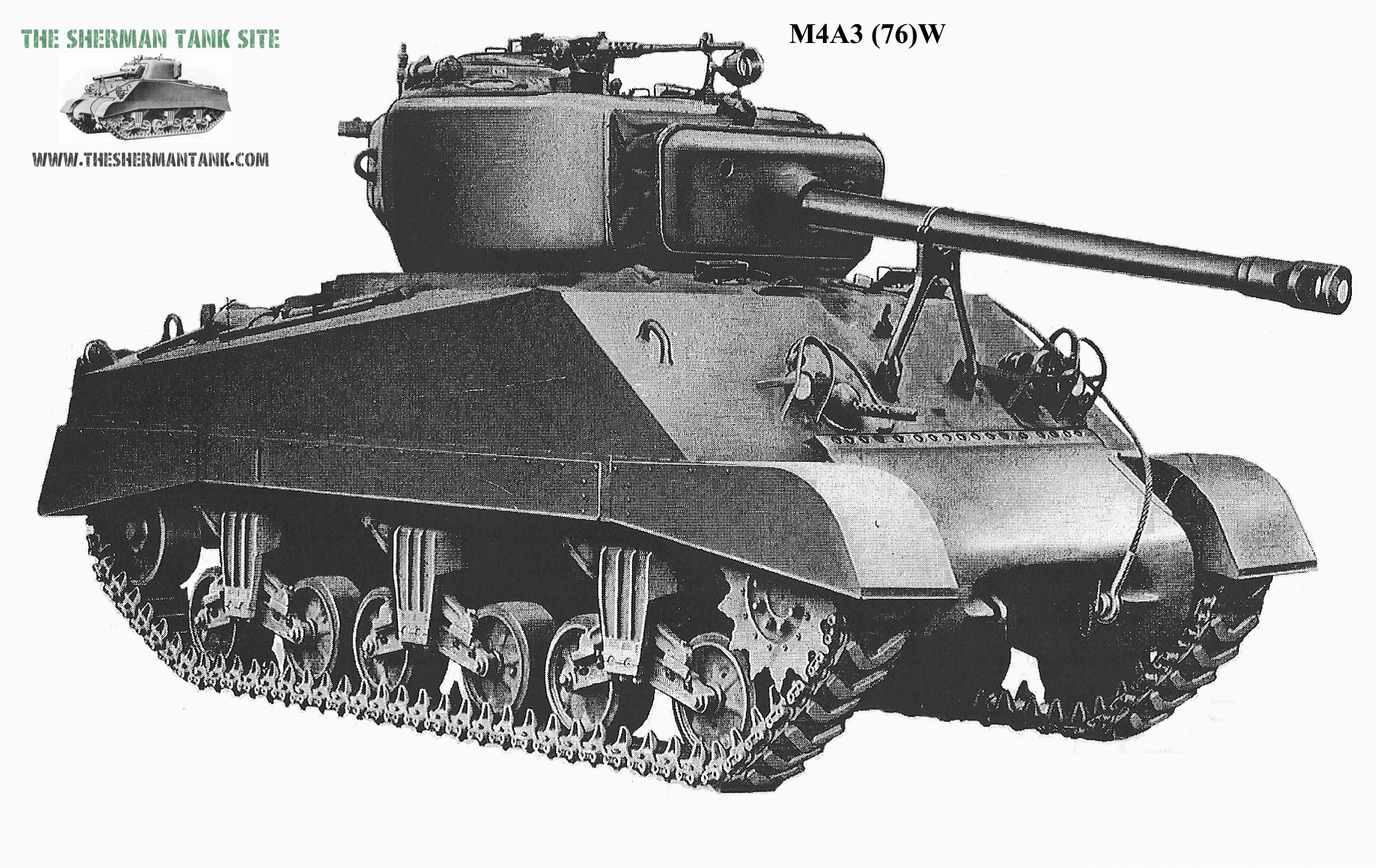
  • M4A3 75W – Even though the Ford GAA was a big improvement, it was not enough of an improvement to take them on as replacement vehicles. They were fine for them to be brought with units already fully trained on them.
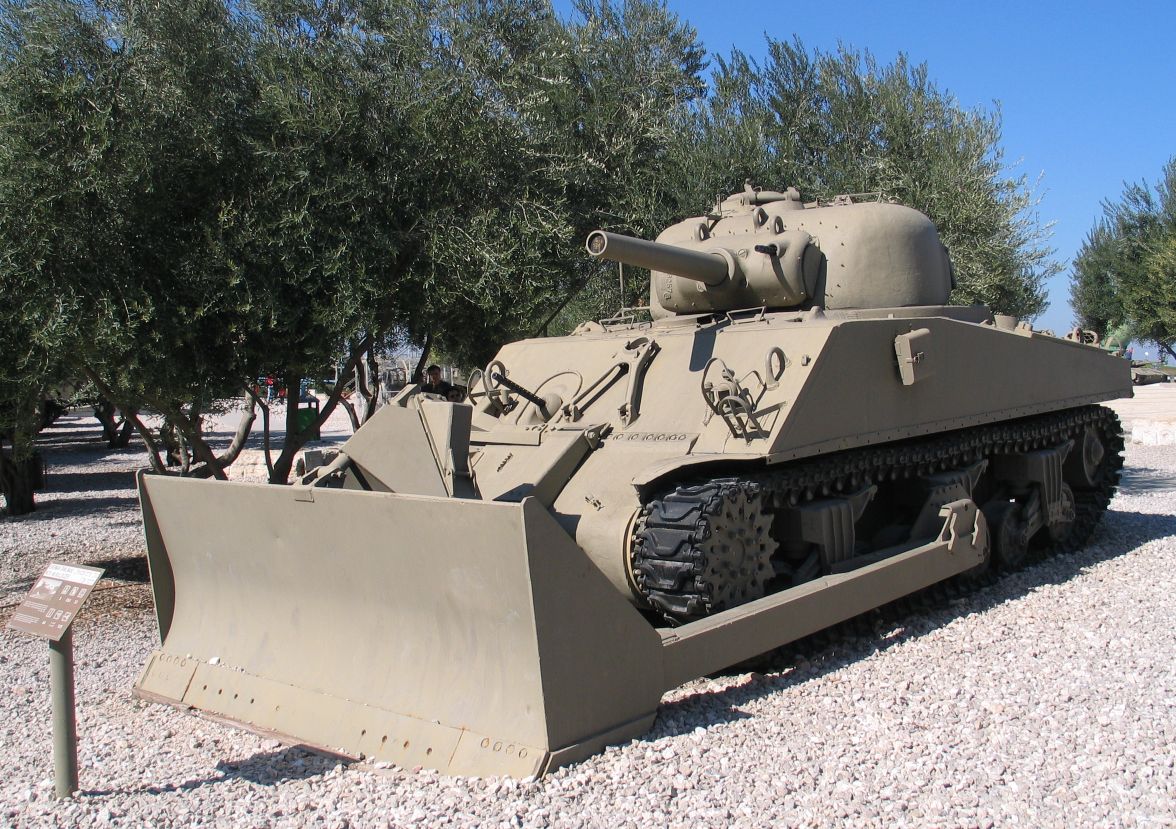
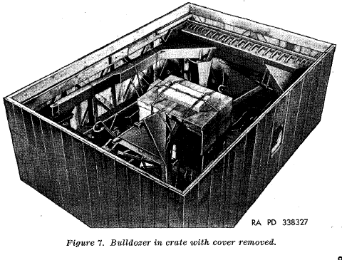
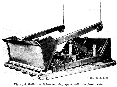
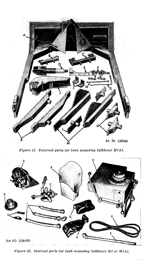
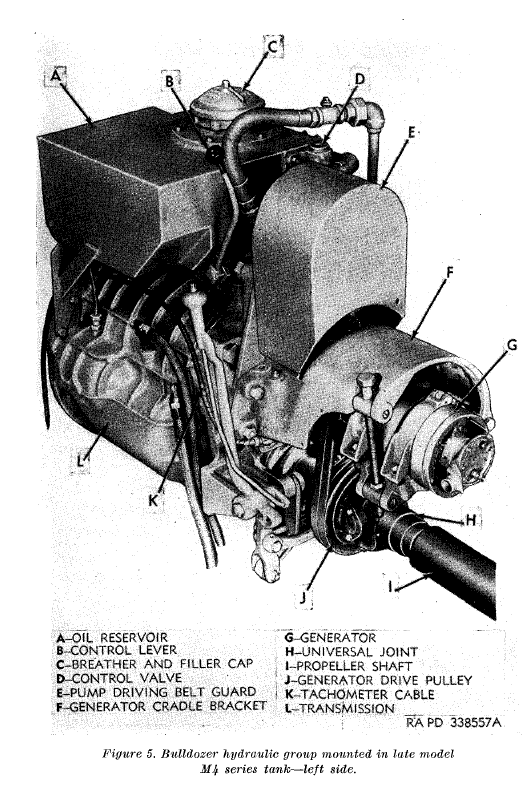
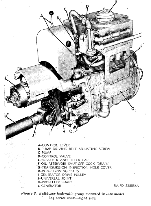
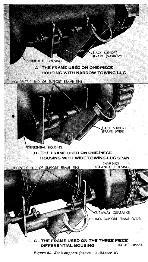
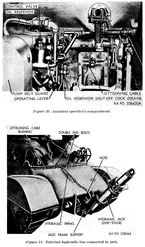
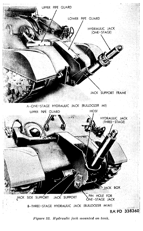
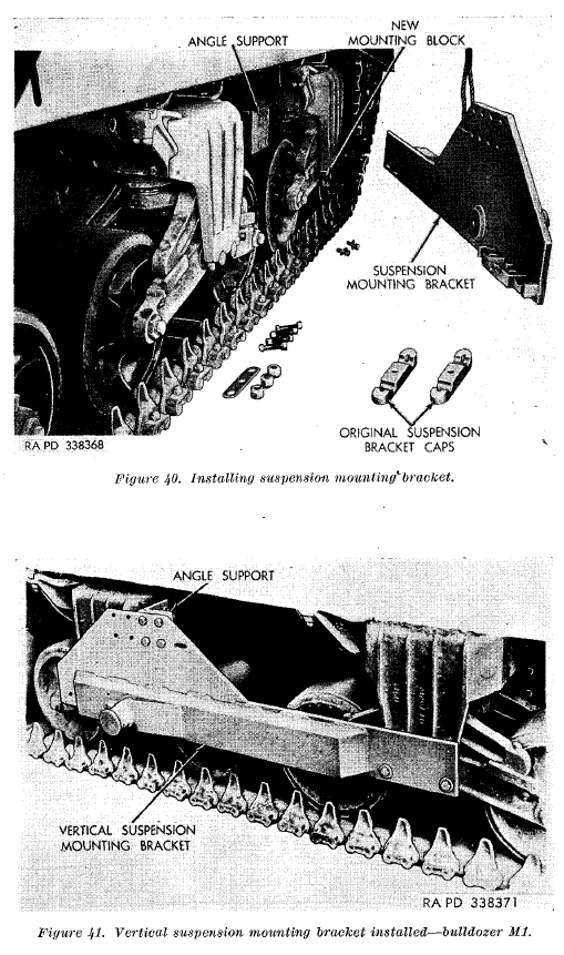
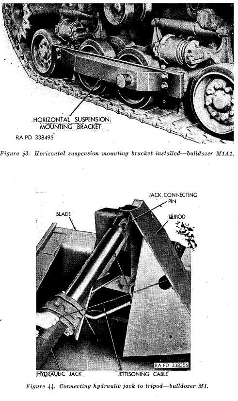
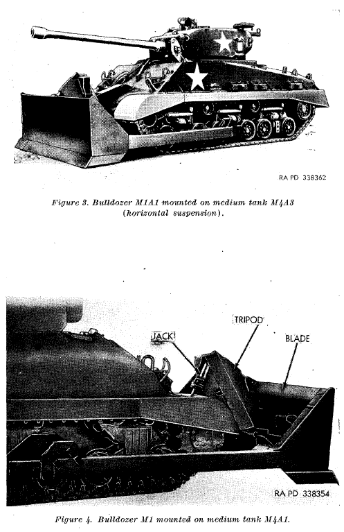
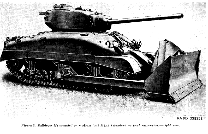
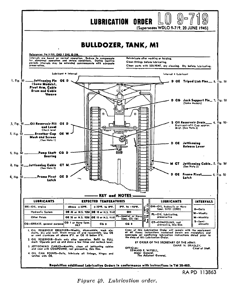
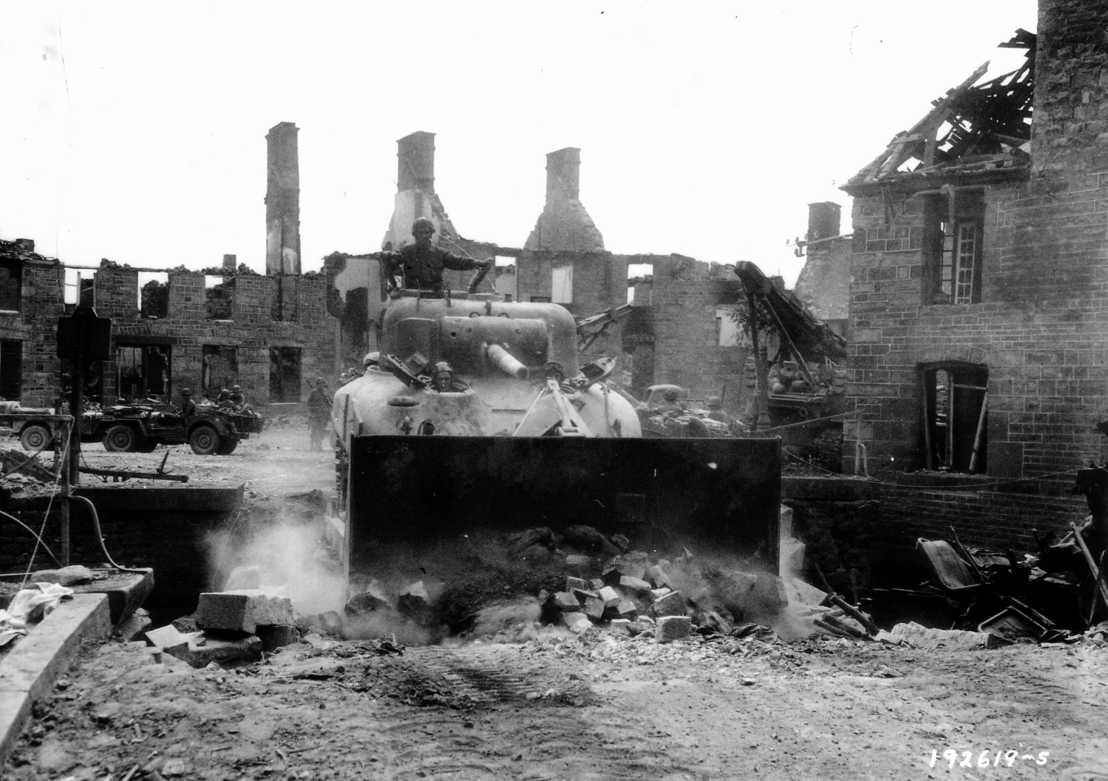
  •  The M1 Dozer blade kit – This kit was an instant hit and would have many uses, including clearing rubble after heavy artillery reduced a strong point.  Currently, this has to be done by an unarmored bulldozer and casualties were high.  it was hoped they would work well enough to help tanks dig in or SPG prepare a position.  ♠ Through testing, they found this kit could be installed on any Sherman tank type.

This report goes into detail in the appendixes listing all the items demonstrated, and where they were demonstrated. They also include data on how many of the various items demonstrated were ordered by the various theatres.

I think it’s pretty clear the MTO was a backwater. The general shortage of spare parts in the MTO and a shortage of personnel to staff the proper echelons of repair and salvage system are also indicators of this. As they got ready for the June of 44 landings, the troops in England would be getting top priority and supplies and spares.

There is a lot of info on other weapons like artillery and small arms, not directly Sherman related and therefore, uncovered here. The report is definitely worth a download and re through.  I think it offers a good insight into the thinking involved on not swapping to 76mm armed Shermans before the Normandy landings.


Sherman Tank Site: News Post 12, pictures and cleaning them up, a lot of them.

Sherman Tank Site: News Post 12, things have been changing, its all behind the scenes.

I’ve gotten my hands on a lot of manuals, and they are all great for gathering info on the Sherman, because you can almost always read them. The picture quality varies a huge amount depending on how it was created. There are some very common and easy to find  Sherman manuals with terrible pictures. For example the two I have on the M4A3, and the manual on the Ford GAA, both were probably photocopied multiple times, then scanned on a really early scanner.

This means, the pictures at best, are mostly black blobs, and even the text isn’t great. All isn’t lost with these, as the line drawings usually come through ok.  In some cases the manuals being sold online are these terrible photo copies printed into a cheap book with no improvements to the quality at all.

Some of these manuals have been scanned in by people with decent scanners, and these though much larger, have much nicer photo quality. Even if the scans are good, the original has to be good as well, and in some cases that’s really mixed.  I have several, scanned at very high resolution, making them restorable, to some degree.

I’ve done the most work on the Ford GAA imaged I have, and the tranny. Here is a selection of the ones I’ve done, but not all. Check out the power train and GAA pages for all of them. These are relaxing to do, and I have a ton to work with so keep checking around the site!

#37 Dozers: The M1 and M1A1 Dozer Blade Kit.

M4A3-Sherman-105mm-Dozer-latrun-1
This M4A3 105 tank has an M1 bulldozer blade installed.

  Dozers: Turn Your Tank Into A Bulldozer!

This dozer blade came in kit form and could be installed on any Sherman. They came two to a crate, an M1 and an M1A1 each per crate. The difference between a M1 and an M1A1 Dozer blade was pretty minor, and an M1A1 dozer blade was universal, but the M1 blade only worked on Shermans with VVSS. This is because the M1A1 blade was wider. Here is some data on the blades. The reason the wider blade worked on the narrower VVSS tanks was because the kit came with spacers to fill the gap left by the wider A1 blade when used on a VVSS tank.


Blade Data

Blade Height: —————————————————————————————-48 inches

Overall width M1:———————————————————————————124 inches

Overall width M1A1:——————————————————————————138 inches

Added weight to tank M1:————————————————————————-7100 lbs.

Added weight to tank M1A1:———————————————————————-7400 lbs.

Lift height of blade M1:———————————————————————18 to 30 inches

Lift height of blade M1A1:——————————————————————18 to 42 inches

Lift Load, M1:——————————————————————————————- 4000lbs

Lift Load M1A1:—————————————————————————————–5000lbs

The TM for the kit makes it sound like it was installed on tanks at the Depot Level and then the tank was issued to a unit with the blade kit installed and ready to go. After reading through the tech manual, it could be done by the tank crew without to much trouble, though a small crane would be nice for the installation of the hydraulic cylinder, but that seems like it would be a rare occurrence. If the kit had a drawback, it was that the blade blocked the bow Machine gun.

bulldozerpic from TM9-719 4 –bulldozerpic from TM9-719 5

The kit broke down into several major parts groups.

bulldozerpic from TM9-719 7

Hydraulic Group: Was made up from external and internal parts that were a part of the Hydraulic system including the pump, an oil reservoir, and all the brackets to install these parts. There were also hoses and fasteners of various types. It also included a special wide angle periscope for the driver. Once

bulldozerpic from TM9-719 2bulldozerpic from TM9-719 3bulldozerpic from TM9-719 10

To install these parts a few things had to be removed from the interior. As this pictures show, the pump and tank assembly was fairly large. Essentially the tray for the spare periscope head box and the box had to be removed. The several brackets and guards had to be removed, and then the generator itself and its mount had to be pulled. It also involves disconnecting the transmission side of the propeller shaft, and installing a new pulley on it to run the hydraulic pump from. Once everything was installed, it did not impede the crew any more than when it wasn’t there since nothing took up the space right above the transmission.

   A few parts from the hydraulic group did get installed outside the tank, the hydraulic hose, run through the left headlight mount. A guard for the hose and a cable running from a handle on the inside, used to jettison the blade in an emergency. All these parts are universal to all models of Sherman, though a few brackets could require a little modification for everything to fit right do to the way some hoses and belts were run.

The hydraulic jack and the framework attacking it to the tanks tow points on the front of the tank are also in the hydraulic group.  There were several bracket sets for use with the different kinds of differential housing the tanks could have.  There was a cover assembly/bracket to protect the mount, and hoses, and help position the jack

bulldozerpic from TM9-719 11 bulldozerpic from TM9-719 8bulldozerpic from TM9-719 10

Suspension Mounting Bracket Group: This group used already existing bolt holes in the suspension to make installation easier.  Each kit came with brackets to make it work with VVSS or HVSS. The VVSS bracket could be adapted to work with either the M1 or M1A1 blades, the HVSS Brackets could only be used with M1A1 blades, because the M1A1 blade was wider to accommodate the wider HVSS. This bracket and had the pivot points for the blade.

The VVSS mounts used a replacement suspension cap built onto the blade mounting bracket, and another replacement cap with bolt holes. Another part of the vertical suspension mounting bracket bolted to the unused return roller holes on the middle boggie assembly, the same one that used the built in replacement caps. The replacement cap with extra bolt holes replaced the cap in the front boggie assembly.

bulldozerpic from TM9-719 12

The HVSS mounts were simpler. You just removed four bolts in the first and second suspension arm supports and install the horizontal suspension mounting bracket with longer bolts and lock washers. This is a much easier install than the VVSS mounts, but neither seems overly hard.

bulldozerpic from TM9-719 13

Once you have the mounting brackets on, you get to move onto the…

bulldozerpic from TM9-719 bulldozerpic from TM9-719 14

Bulldozer Blade Group: This group is basically the blade and it arms that mount to the pivot points on the suspension brackets.  This part of the job is where you could really lose fingers or toes. You need a nice flat area, the area you stated in hopefully, and then you drive the tank up to the blade, careful to keep it centered. The tank stops to feet from contact with the blade, and the driver raises the jack piston to the same as the connecting pin on the Blade group.

This is a multi-person Job, since the co-driver has to hold the quick release cable, in the release position, while the tank is driven into the Jack arms pivot points, and then let the pin close on the eye on the Jack head. The co-driver, while doing this is also guiding the tank into place on the blade arms. At this point the latches on the pivot points can be locked down, a large hammer may be needed and the quick disconnect cable fed into place and loosely connected in the interior of the tank. When it’s pulled the whole assemble will come lose and can be backed out of.  You can see some of this in a video in the Shermans in motion section.

bulldozerpic from TM9-719 16

The final step would be installing the M14 periscope in the drivers position, filling the system with fluids and testing it out. The system was easy to use, and had dual controls, so the co-driver could operate the blade if the driver really needed both hands. The controls were a simple lever used to raise and lower the blade, raising it by hydraulic pressure, lowering it by cutting the hydro pressure and letting the weight of the blade bring it down. Removing the blade was as simple as pulling the quick release cable. If you planted the blade in the ground just right before release, so it wouldn’t move, you could drive the tank right back up to it, hammer the pivot point latches in place, put the pin in the jack and go.

I have to say this is a very impressive kit. It did make the tank a bit front heavy and probably shortened the life of the front springs, it was not a problem in any real way or the Army would have had modifications made to solve these problems. This kit saw prolific use with the US Army and Marines, and since it worked on any Sherman model, probably everyone else who used Shermans and could get their hands on it. This dozer kit was the most effective way of punching through hedgerows as well, working much better than the dedicated hedge row cutters. A tank company would get one dozer blade equipped tank into the HQ platoon, if there were enough kits to go around. There might be another one in the Battalion HQ platoon.

bulldozerpic from TM9-719 15

The Lone Sentry has published a report from Shortly after WWII called the Armored Special Equipment report.

This report covers all the armored funnies, or specialty vehicles from Hedgerow cutters, DD tanks, and Crab modifications. Our interest from this article is the feedback on the Dozer blade setup.

This was the feedback on its combat use:

The tank dozer was employed extensively for numerous purposes commencing immediately after D-Day. Some of the missions for which the tank dozer was employed in the European Theater are outlined below:

(1) Shortly after D-Day a platoon of four tank dozers of the 741st Tank Battalion operating on the beaches under intense fire, removed beach obstacles, opened roads and pushed off beached landing vehicles.4

(2) The tank dozer was used to break through hedgerows, broaden existing gaps and gaps blown with explosive charges; and thereby facilitated the use of other than normal entrances through hedgerows.5

(3) Tank and gun emplacements were prepared.

(4) Roadblocks were cleared; and in addition, rubble, wrecked vehicles, and snow were removed, and craters filled. It was found necessary in many instances to provide a tank dozer for these purposes to work in conjunction with the roller type mine exploders in sweeping roads and shoulders.

(5) In connection with the Roer and Rhine River operations, bridge approaches were built, launching sites for LCM’s and LCVP’s and crane sites were prepared, and cuts dozed in the river dikes.

The Tank Dozer has the following merits and deficiencies:

(1) Merits:

(a) The tank dozer provides armored units with a standard vehicle that can be readily employed to reduce obstacles and assist in the advance of units or to assist in the preparation of defensive positions.

(b) Armor protection is provided for the crew.

(c) The tank dozer can also be employed as a fighter tank.

(d) The tank dozer installation is simple, reliable, and its maintenance demands are negligible. 

(2) Deficiencies:

(a) The tank dozer installation overloads the front of the tank suspension system and increases bogie tire failures and suspension maintenance demands.

(b) The tank dozer installation materially limits the driver’s field of vision.

(c) There is insufficient clearance between the track and dozer blade arm to ensure safe operation with the addition of the standard 3-5/8 inch track extended end connectors.

(d) Sufficient dozer blade accessories were not available so that dozer blades salvaged from burned tanks could be readily reinstalled on other tanks.


I found this very interesting, please check out the Lone Sentry Web site, it’s a very informative place.

The source for this post was almost exclusively Tech Manual 9-719 Tank Mounting Bulldozer (M1 and M1A1). The TM can be found in our download section and the report on the lone Sentry.

Here’s a video from the army on how to install this dozer blade kit.

https://drive.google.com/open?id=0B5k30qNybbcZbm1HLTkwU1FUOWs

#36 The Transmission, Differential, and Final Drives: Called the ‘Powertrain’ and It Was Great On The Sherman!

The Transmission, Differential, and Final Drives: Called The ‘Powertrain’ The Sherman’s Was Very Well Designed.

Sherman transmission

The Transmission, differential and final drives on the Sherman were very robust from the start of the Sherman design and proved to be rugged enough to take all the upgrades the Sherman had thrown at it over the years. As a combined unit, along with the steering brakes, with the armored differential housing they were referred to as the ‘powertrain’. In most cases a whole powertrain unit would be swapped if any of the major components needed serious work, since it was relatively easy. There were three types of armored covers, a three piece bolt together type, and two cast types. Powertrain units incorporating any of the differential covers could be swapped into any Sherman in place of any other type of powertrain unit. The internals of the three types of differential covers where different though and parts in some cases do not interchange. Hydraulically powered steering was tried on very early M3 Lee tanks, but it was discarded for an all mechanical long lever system used throughout the Lee and Sherman run.

latemodeel powertrain diagram

The final drives and differential had a gear ratio of 2.84:1, limiting the tanks top speed by RPM to 26 miles an hour in the M4A3 version of the tank, and that for only short burst. The RPM limit varied with engine model, and in the Jumbos case, a slightly higher gear ratio of 3.36:1, limiting its top speed to 22 miles an hour but giving the drivetrain a little more mechanical grunt to get the extra weight moving. This was the only modification major enough to be mentioned in any publication I’ve read so far. That says ‘damn good design’ to me. I’ve read several accounts of Sherman restorations being done, where after years on a firing range, or just rotting in a field somewhere, the final drives and differential units needed no mechanical restoration.

M4A2 differential cutaway
Cutaway of an M4A2s differential
M4A2 Final Drive cuttaway
Cutaway of a Sherman final drive.
m4a3finaldrive
Sherman final drive herringbone gears and shafts. This image is from the American Fighting Vehicle Vehicle Database.

Now a bit about gear ratios, for those who are not gearheads, before we get into the transmission since it’s going to have even more confusing gear ratios talked about. The meaning of the gear ratios in the above paragraph is, for every rotation of the drive shaft coming out of the transmission and going into the final drives and differential has to spin 2.84 times to spin the sprocket output shafts one turn.  What determines the Transmissions output rpm is what gear it is in, and what ratio that gear is.  The higher the number, the more mechanical advantage is transferred to the final drives, but lowers the top tanks tops speed in that gear.  If you have driven a manual transmission car, this is why first gear climbs in RPM so fast and each further gear the RPM climbs slower, but the car goes faster, same for the Sherman tank. If you really understand this, you will always get a laugh at the Hollywood portrayal of nitrous oxide; something used in WWII aircraft engines because they always show it as making the cars top speed faster, when all it can do is improve the acceleration to the mechanically limited top speed.

page1-1076-full
This M4A3 Powertrain is about to go back into its hull

The Sherman transmission has a “Granny” first gear ratio of 7.56:1, the tank isn’t going to be moving faster than 1 or 2 miles per hour before the driver would have to shift.  The next gear up, second is 3.11:1, on level ground, gear two is used to start the tank and drive it at low speeds. Say up to 5 miles an hour, on road and rarely off road third rarely you would then get into third gear, 1.78:1, and up to 8 to 10 mph.  Fourth would be the last gear to see regular use, coming in at an almost one to one, 1.11:1. This is your driving like a bat out of hell 13 to 19 miles an hour gear. Fifth gear is actually an overdrive gear, at 0.73:1, meaning .73 of a turn to spin the tranny output once. Meaning, this has to be taken to into account in calculating the tanks top speed and it could only reach its top speed on good roads in fifth gear! Reverse gear, 5.65:1, was almost as tall as first and really limited the tanks reverse speed. If you understand what be just covered, you can understand the gear ratios listed on your next cars window sticker.  On our example, M4A3 at would be screaming along at 2800 rpm, at the tanks 26 mph top speed.

powertraincutawaylabeled

Now that you understand gear ratios you may wonder what the term “Granny” gear means. The ‘Granny’ gear refers to a really high gear ratio gear, almost always first. The Granny gear was used for getting a vehicle started while hauling a big load, trying to tow another tank to get it started or heavy vehicle for the same reason, climbing a steep hill or obstacle, driving through thick mud or deep water or getting another tank or heavy vehicle unstuck from mud or another obstacle. This gear could also be used to slow the tank when going down a steep hill.

Powertrain early, from M4A4

The Sherman Transmission was fully Synchromesh in gears 2 through 5 with first and reverse not needing it.  Synchromesh means you did not have to depress the clutch twice, once to get it into neutral, the next to go to the next gear, or “double clutching”. This, in theory, made the Sherman tank, though a manual transmission that used a clutch, much like any car that has a manual, relatively easy to drive. If you could drive a car from the 30s you could drive a Sherman. There are several Sherman museums that will let you drive one if you have the right amount of money.  From what I understand, the key to how easy the Sherman is to drive comes partly from the motor in it and partly from how much you’re really willing to drive the thing and not worry about breaking it. It’s an American tank people, you can abuse it, it can take it, it’s not a Panther, it was designed with the American young adult of the 40s in mind. Hell, these things were used to tear down buildings post-war! They are not delicate.  Anyway, back to what I’ve read about driving a Sherman. The easiest motors are supposed to be the Diesel and Ford GAA, then A57 if it’s running right, then the R975 powered tanks. The R975 because it likes to get up into its higher RPM power band, and stay there for a while, it helps burn off carbon and keeps the plugs un-fowled, is supposed to be the hardest to drive. In contrast, the few places that have running Panther tanks have to be extremely careful who they let drive it since using some of its design features could destroy the transmission or final drives.

powertrain brake adjeuxtment

The Sherman powertrain was a very tough unit. I know of at least two restorations where the transmission needed little mechanical work. This same transmission, and for the life of me I don’t think I’ve ever seen a name for the original designer/maker, stayed largely unchanged through the full life of the tank. The Israeli Shermans used into the 70s were using original Sherman Transmissions, though probably overhauled. That they could be, and continue to be on overhauled for restored Shermans, kept working, and working well after all those years also screams “DAMN GOOD DESIGN” and it’s a little sad I don’t, we don’t know, who made them or designed them.

rear firewall m4a3 late
The oil cooler shown in this diagram was found in all Sherman models.
page1-1053-full
This powertrain out of an M4A3 76w tank sat for years, after being abused in a tank used in the demolition of houses. It only needed cosmetic restoration.

#33 The Sherman Of The Future: Advanced Sherman UpGrades That Almost Made It Into Production.

The Sherman Of The Future:  So Many Very Interesting Technological Marvels Almost Made It Into The Sherman

This is a long one guys, but well worth the read if you like geeky old technology stuff

The US Army was always looking for ways to improve the basic Sherman tank. Some of these didn’t pan out because they just were not that much better than the basic M4, or the US Army had no interest, or the war ended production of the Sherman before an improvement could be fully developed, or in some cases, just added to the production lines.  These ranged from whole new tanks based on the M4, like the T14, or in some ways like with the T1/M6, to improved guns, engines/transmissions to aiming devices.

Let’s start with Armor:  Add-on kits, they got developed but were never used.

Wooden mockup CDA
Wooden mockup CDA


Bolt-on armor kits: CDA was asked to develop a set of bolt-on armor for the Sherman, there are pictures of wooden mockups, but this program was canceled before the second gen large hatch hulls started production. At this point, the best source for info on this program is R.P. Hunnicutt’s Sherman. He does not note why it was canceled. It seems like with the success of the M4A3E2 Jumbo, and it’s only marginal effect on the reliability of the automotive components of the Sherman, this would have been a hit with the troops.

Up-armored differential covers: There was another program to improve the armor of the early differential covers. Both the early three-part bolt-together designs and the early one-piece cast designs, were found to have areas more vulnerable to penetration than the rest of the differential cover. They came up with add-on armor for each type. After testing these kits were found to be good enough to make the differentials the best protected front area of the tank after installation. The Army approved them, but no evidence of any being used has been found. The final production cast differential cover was improved and would not have needed these kits. That may have been the reason the kits didn’t get used since they could just use the ultimate production casting when doing rebuilds.

plasticsherman armor shermanspikes

Plastic armor and spikes: When the threat of AT sticks like the panzerfaust become more prominent, an add-on armor kit made from called the HCR2 plastic armor kit was developed. It was made from a mixture of quartz gravel and a mastic compound made from wood flour and asphalt. It was held on by cables and could be jettisoned with ease. The armor from this kit protected the Shermans turret well, but sponson penetrations could still happen. It also offered a little extra ballistic protection. It also did not cover the front of the hull or turret.

Another attempt to defeat shaped charged weapons involved installing spikes in lengths varying from 7 to 8 inches all over the armor. The idea behind this was to break up a heat warhead before it could detonate properly.  Testing on this continued after the war.

Now let’s talk about improving the tanks less passive defenses:  Improved Machine Guns and Flame Projectors!

The vulnerability of the Sherman, like any other tank, to close infantry assault was a problem the U.S. Army was always looking to solve.  This is why the Sherman prototype retained the .30 caliber mini-turret on the commander’s hatch. This was a hard to use and unpopular cupola, that did not make it onto any production Shermans, but that wasn’t for lack of trying on the US Army’s part.

Improved ball mount with sight: The first thing we will cover is the improved ball mount for the co-driver/BOG. What they did was come up with linkage at connected the bow mounted .30 caliber machine gun to the gunner’s periscope. The co driver’s periscope would have a telescopic sight much like in the gunner’s periscope. The linkage and sight allowed much more accurate use of the bow-mounted machine gun. Only the cessation of production on the Sherman stopped this one. It would have been useful if we had to invade Japan.

krQqXCz
Line drawing of the sight for the bow machine gun. This image came in from our reader Whelm, thanks again Whelm!

M3 grease gun adapter: Another interesting defensive device they came up with was a special adapter for the M3 grease gun that allowed the gun to be hooked up to a curved barrel extension fitted to a standard rotating periscope mount. Then a special periscope with sight could be installed and the M3 fired and aimed from inside the tank. It was found to be accurate enough to engage targets within 33 yards of the tank. I suspect this one didn’t make it into production because it seems like more trouble tank it would be worth, but it is still an interesting idea.

Co-ax M2 and M1919: A more conventional way was the installation of an M2 .50 caliber Machine gun, alongside the .30 caliber M1919 machine gun, mounted coaxially with the main gun. This would have worked out better if one of the advanced guns mounts using a concentric recoil system had made it into production. I’ll cover these mounts later in this post.

The T121 twin machine gun mounts: This mount replaced the all-around vision cupola on the commander’s station with this rather large twin machine gun mount. The mount could take the M2 or M1919. This was a remote power turret and could be operated without being exposed. This mount missed the war, and development continued on it post-war.  It was very tall, almost as tall as the Sherman turret by itself.


Fragmentation grenade mounts, mines, and pipe bombs: The Army decided to try mounting these on tanks and test how they would work to combat close in enemy infantry as a kind of last resort weapon. This did not work very well and only the grenades were found to have an effective fragmentation effect. They all risked damage to the tank so they were dropped. Shielding to protect the tank made them even less effective.  None of these worked as well as having close infantry support, and the idea was dropped.

aaaaav5y6EJ0phosprojectpr phosprojector

The Scorpion/Skink anti-personnel flame projectors: This might have seen use if the war had gone on. This is just the type of thing to use on Japanese suicide troops if they have scared or killed off all your close infantry support. This system had four self-contained, phosphor based, flame projectors mounted at each corner of the tank. Each one could let off 20 to 30 bursts of the flaming phosphorus in a fan from each device, giving great coverage all around the tank. They could be fired off individually or all at once from inside the tank.

Now let’s talk about two vehicles that almost made it to production: The M4 Improved and T14.

M4 Improved M4 Improved2 M1 improved and M7

The M4 Improved or the idea behind an improved M4 started just about as the time the first production Shermans were rolling off the line. The proposed new tank design that came along was very interesting but not deemed enough of an improvement to change up the production lines.

Since the tank didn’t make it into production, you would think it would be hard to have an idea what one would have looked like. Normally that would be the case, but the game World of Tanks has added the M4 Improved as a premium tank, and they did a beautiful HD model for it.

The proposed M4 I would have used the same M3 75mm gun, with a welded turret, and an improved hull with thicker, sloped armor. It also used a modified version of the M6 heavy tanks suspension, a complicated precursor to the HVSS suspension installed on late production Shermans. It would have used the 625 horsepower Wright G200 motor. Considering the US Army would have just been getting their hands on their first Soviet T-34, I think you can see the influence the T-34 had on the M4 Improved. The wide tracks and extra slope in the side armor being the most prominent.

Even though the improved Sherman had some big flaws, like putting the gas tanks under the turret floor, many of the improvements would be refined and make their way into the later improved Shermans. The suspension is clearly the father of the HVSS suspension, and the tracks probably showed the advantages of center guided tracks over end guided, at least on suspension that wide.

The T14 Heavy tank: They even made a few of these things.

033-1024x685 14485009400_649955abf0_b

On March 30th, 1942 representatives from Chief or Ordnance, Aberdeen Proving Ground and the British Tank mission had a conference to discuss tank stuff.  The need for an assault tank was established at this conference, pushed for by the British. The US Army had no interest in an assault tank at that time. It was decided the US and British would each produce a pair of pilot tanks, and then the better of the two would be put into limited production.  The Brits would go on to produce their assault tank on the Cruiser VIII, and the US would use the M4 as the basis for theirs.

By June they had finished the requirements, design, and wooden mock-up, and American Locomotive Company was contracted to build two real tanks. Pilot 1 was finished in July of 43, and the second one was done a month later.  The pilot tanks used nearly the same suspension that was proposed for the M4 improved the horizontal volute spring suspension out of the M6, and the same M3 75mm gun the standard M4 carried.  It also carried an M2 .50 caliber machine gun in the bow and a 1919 coax with 75mm gun. It would have also had either an M1919 or M2 for AA use mounted on the commander’s hatch.

The Tank used a Ford GAZ V8, a slightly uprated GAA. Other than the motor, and a final drive gear ratio change, the automotive components were standard Sherman fare.  The tank came in at 47 tons and had a pretty good armor. The Armor was much better than the standard Sherman but not as good as the later Jumbo, and there was really nothing the US Army found interesting about the tank. The design was supposed to have the provision to take bigger guns, and it had the same 69 in turret ring as the Sherman, but it also had problems.

It was a dog, the GAZ had trouble moving the 47 tons around. The track system was not very good at this point. Tracks were easily thrown in testing, the tanks armored skirts made getting the tracks back on a pain. Even with the wide tracks, it wasn’t very mobile. It did have a scope for the BOG to aim his gun with, so it had that handy feature going for it.

Pilot one was shipped off to Fort Knox for further testing, and pilot 2 was sent to England. It is still there, and it seems to be in ok condition. It’s at the Royal Armored Corps Tank Museum at Bovington Camp in Dorset. None ever saw any kind of combat, and the program was canceled in 1944 after no one showed any interest in the tank.

Practically space-age improvements that almost made it: Sherman advanced gear, multi-axis stabilizers, better gun recoil systems, better tranny and motors.

Concentric recoil systems: The Army had seen how good a concentric recoil system was from the one used on the M24 Chaffee.  Late in the war, they had Rock Island Arsenal working on a similar mount for the 76mm M1A2 gun. A normal tank gun recoil system has a pair of cylinders on both sides of the gun to absorb the recoil energy of the gun. These systems are pretty bulky.  A concentric system uses one larger hollow cylinder and the gun is mounted inside it, this works better and saves space, it was named the combination mount T103.  There wasn’t much of an advantage in combat, but it would have allowed more room in the turret for other gear and ammo. It also would have left room for the M2. 50 Caliber machine gun being mounted along with the regular co-ax gun.   This system was being tested and was doing well, when the war ended, ending any chance of seeing the mount on new production Sherman tanks.

The rigid gun mount: Yeah, just what it sounds like, the tank is the recoil system.

The rigid gun mount: A rigid system has a lot of advantages; it takes up way less room in the turret. The gun doesn’t retract into the crew space on firing making it safer, and you don’t need any kind of recoil guard. A rigid system is probably lighter too, but the mount has to be pretty beefy to handle the loads.  They designed the gun mount to take both the M3 75, and M1A2 76 guns, and it was tested with both.

The gun was mounted in a lightweight turret, and then onto an M10 hull. Test firing showed the stabilizer and turret race bearing took no damage, but the turret hold down bolts had stretched, and some threads were stripped.  Larger stronger bolts would solve that problem, and when installed in the heavier Sherman turret, would absorb the recoil better than the lightweight turret it was tested on.

Can we all guess what killed this one off? Yep, the end of the war, boy, if the Japanese had held out, they would have been really sorry.

The two-axis stabilizer: Two axis stabilizers almost made it in.

The Army had seen through battle experience crews trained in the use of the Shermans stabilizer had an advantage over the ones who didn’t. Unfortunately, during WWII it was all to common to find units who were not in the systems use. So a very advanced system, something the Germans could not match during WWII, often went unused because of poor training.

The late production stabilizer in Shermans was simplified and easier to use. Experiments at Fort Knox found there was some backlash in the system, and they solved it at first with weights, and then later with a minor modification on how the stabilizer worked.

Once the elevation stabilizer was improved, the Army started to look into and azimuth stabilizer.  International Business machine had a design and it was tested at Aberdeen in late 43. At first, the design did not work well, but after a series of modifications, they got the system working well enough to test. At the same time Ordnance came up with their own design, using off the shelf components, and it was ready for testing around the same time.

During the testing, they used M4A3 75 tanks, a standard tank, and then one with each IBM and ordnance systems. The crews would be rotated through all three tanks to eliminate crew experience in one tank changing the results. The IBM system worked better than the ordnance system, but the ordnance system was much easier to adapt to the Sherman already in the field.

If you sensed a theme here, then you know what’s coming, the war ended before any of these two axis systems could see combat use. The Ordnance system was fitted to a 76mm Sherman and testing of the system continued after the war, comparing it to the Vickers system the Brits came up with. The Ordnance system needed to be beefed up and made more resistant to vibration, and what was learned here was probably passed on to later designs like the M26.

Better Motors: Motors that never had a chance or almost made it

V65

Chrysler’s A65:

This was a huge V12 that Chrysler designed on their own dime. It was 1568 cubic inches, was gas powered and made 650 gross horsepower, and 580 net HP, and was water cooled. A test installation was done to an M4A4, and they had to lengthen the hull another 9 ½ inches to fit the mammoth motor. The tank only weighed around 500 pounds more with the motor in. The tank was a real hot rod and climbed hills better and out accelerated the standard M4A4. Even after dropping the final drive gear ratio from 3:53:1 to 3:05:1, and it still out climbed and accelerated the standard M4A4 and even the M4A3.

After 400 miles of testing, the engine was pulled and examined and found to be in perfect running order.  The project closed with the Army recommending further study on engines in this power range.

Vb184gmdesiel

General Motors Corporation V8-184 diesel engine:

GM developed this as tank motor, it was based on a large marine diesel cut in half, and was still very large. This V8 diesel motor came in 1470 cubic inches and 3750 pounds. It made 600 gross horsepower at 1800 rpm and 1910 foot-pounds of torque at 1000 rpm. The motor ran at a 16.8:1 compression ratio.

One test versions of this motor were installed in an M4A3 hull and tested. It was called the M4Y at first, then when ordnance started testing it, it was re-designated and M4A2E1. The tank had to be stretched 11 inches and lost a little ground clearance to a bulge in the belly needed to fit the engine. They put 2914 miles on this test vehicle and it was another hot rod. It had much more power than any other Sherman but the A65 powered one. Some minor mechanical failures happened during the test, but nothing major or out of the ordinary that couldn’t be fixed. Nothing needed any kind of major redesign to support the power of the motor.

Much like with the A65, a diesel in this power range was going to be studied due to the success of the M4A2E1.

Caterpillar D200A air Cooled Radial: The motor that made it into 75 Shermans

rd1820rear rd1820front

This motor used a large number of Wright G200 components and modified it with a bunch of Caterpillar parts. At some point, I may go into detail on how they did this, but for the moment, if you really want to know, the section in Hunnicutt’s Sherman book starts on page 167.

This motor made 450 horsepower at 2000 rpm and 1470 foot-pounds of torque at 1200 rpm.  Good, but not great.  It did perform well enough to get into production, but after only 75 M4A6 tanks production was canceled and the tank was regulated to stateside training use.  This motor was no hotrod power plant like the other two, but I had to fit it in somewhere.

♠♠♠

A few other diesel designs were tried, but none worked as well as the V8-184, and they were all dropped early in their design period.  There is also one motor we have not covered, the motor that powered the M4A6, the Caterpillar G200A air-cooled radial.

One thing to note about all the high horsepower Sherman tanks, none of their other drive train components saw major modification, because they did not fail.  So a transmission and final drive designed for a 400 horsepower 30-ton tank, had no trouble taking 650 horsepower from the monster motors above, or any trouble handling the 42 tons of the M4A3E2 Jumbo.  To me that says, well designed, in that it was very overbuilt, and lasted a very long time. The Transmissions and final drives just kept on working, and all the post-war Sherman modifications used the same old tranny and final drive.  That’s the kind of engineering that people should consider to be great. Not some German, garbage tank, named after a cat, which broke down every 150 kilometers.

Now let’s talk about transmissions, final drives and other automotive tidbits: The stuff that makes the tank go.

Like with the motors, many different transmissions and final drives were experimented with. Nothing was so groundbreaking it made it into production, but much of it helped develop transmissions and final drives in later tanks. There were other automotive odds and ends we’ll cover too.  Starting with …

The high-speed reverse transmission: This transmission modification came out of the desire to speed up the Shermans reverse speed. The reverse gear ratio was 5.65:1. This was almost as high as the ‘Granny’ gear used in first gear. This meant the Shermans speed in reverse was rev limited to a 2 to 3 miles per hour max in reverse. The tank was geared this was so it could climb a hill in reverse if it had to. There are cases on tight roads or trails in forests or cities you can’t get the tank turned around.

The first thing they tried to solve this was raising the gear ratio, and this did speed up reverse, but it made it extremely hard to climb any hill or incline.

The way they solved this problem was by adding a secondary planetary gearbox to the back of the transmissions. This allowed the whole transmission to be reversed, allowing all five speeds to be used backing the tank up. This new add-on gearbox including a new low-level oiling system that reduced the oil capacity from 43 to 20 gallons. This modification lowered the operating temp of the tranny and transmitted 25 more horsepower to the sprockets.

The drive shaft mounted generator had to be moved and the drive shaft had to be shortened, but that was the extent of the modifications needed. The shorter drive shaft also worked better, deflecting less, so the universal joints lasted longer. After testing the transmissions for nearly a year they were enthusiastically endorsed as far superior to the stock unit.  Can you guess why these wonderful transmissions didn’t make it into the Sherman? You guessed it, the war ended and Sherman development and production stopped.

Next up, automatic, or semi-automatic transmissions, because driving a stick is hard:

The Spicer 95, General Motors 3030B Torqumatic, and the Model 900T were all considered for use in the Sherman. The Spicer unit was in testing as the war ended. The 3030B was discontinued by GM before it could be tested.  This was the transmission used in the T20 and T20E3. The 3030Bs replacement was the 900T, but it was in high demand from the M18 Hellcat program. They went back and used Spicer 95s to test the concept. By mid-1944 GM was able to more than handle demand from the M18 program and was able to furnish test transmissions.  Two M4A3 tanks were modified and re-designated M4A3E3. They were then sent to Aberdeen Proving Ground for testing against the Spicer 95 equipped M4A1E3 and M4A3E1 from the early tests. The tests were promising, but the end of the war and the cross drive transmission in the works really killed this one off.

The Cross Drive Tranny/Differential: Work on this new type of transmission/final drives started in early 43. What would be developed from it would be the standard transmission for post-war US tanks. It was designed for not just use in the Sherman but later model tanks as well.

Shermancrosdrive

Model EX100 Cross Drive Tranny: This was the first cross drive tested the US and it went into an M4A3 Sherman. The installation in the Sherman required a large hole to be cut in the upper part of the Transmission cover, and a large bulged armored cover was placed over it, to fit the new transmission. This cover was called the “manhole cover”, by engineers and the tank maintainers.  The was an automatic transmission using a torque converter, with electric steering and braking, and all in a much more compact unit than the Shermans current transmission/final drive setup. There were of course problems, and since work on this started late, when they solved the problems, it was no longer for use in the Sherman.

Suspensions: The ones that didn’t make it, I might throw a bit in about wider tracks here too.

Seemly like every other part of the tank, there were extensive tests of various types of suspension on the Sherman. When we talked about it before we only covered the suspension that made it into production.

Early HVSS: This was an attempt to increase spring life but used the same width track. This was also the suspension used on the T20, T22, and T22E1. These units had shocks in the front and rear bogie units, and they made the ride more smooth and had a favorable effect on gunnery and overall ride. It did not, however, offer enough improvement for any slowdown in the production lines so it was never mass produced.

Christie Style: A heavily modified version of a Christie type suspension was tried on one tank. The springs were installed on armored boxes under the sponsons but outside the hull. It showed it was feasible, but no one was really interested. Christie suspension may be the most overrated suspension for a tank ever.

M4A2e4
M4A2e4

Torsion Bar: In March of 1943, Ordnance recommended a design and construction of a Sherman tank with wide tracks and torsion bar suspension. This type of suspension had been seen on German tanks like the PIII and Stug, Russian tanks like the KV series. Two M4A2E4 tanks were produced for testing. These tanks borrowed a lot from the T20E3 since it was getting a torsion bar suspension a too and it would use the same 24-inch wide track. The suspension offered few advantages over the HVSS system that reached production and the test vehicles had a lot of problems with things breaking. It did provide valuable information about the torsion bar suspension that would go on to be used in later tanks, and it had a very low 10 psi ground pressure.

World of Tanks gave the in-game version of this tank away to the North American Beta testers when the game went live,  and it’s always been one of my favorite in-game tanks.

Leaf Spring: Yeah, just like what it sounds, paired leaf springs, six per side and it didn’t work well. It didn’t go far either

T16 Halftrack truck “Centipede”: This suspension was overloaded and didn’t work well, and looked really odd.

Heavy Tractor T22:  Looked a little like a combo of the early VVSS suspension and late HVSS, but overloaded and it did not go anywhere.

Odds and ends: Weird stuff I couldn’t fit anywhere else.

This section is going to cover the numerous odds and ends that don’t fit elsewhere, anything from the proposed crew compartment cooling system to the auto-mapping system etc.

Let’s start with…

The Odograph: This was an early auto-mapping/navigation system that used a magnetic compass and data from the speedometer drive to keep track of the movement of the vehicle on a chart. This worked well enough in a jeep, but all the steel of the tank messed with the magnetic compass. Once we were no longer fighting in the desert where navigation could be troublesome support for this program fell off. They installed this in the M4A1E2 and had it working, showing just what 40s tech could do.  This project led to further development of magnetic compasses for the Sherman and tank use in general, so the program was not a waste of time.

The crew compartment cooling system: There was a project to put a crew compartment cooling system on the Sherman. This was very early in the tank’s production, and an M4A1 was selected as the test vehicle and redesignated to M4A1E2. The lined the interior with insulation and put an evaporative cooling system in. The system did not work all that well, and demand for it dropped off when the fighting moved out of the desert. The project languished and was eventually canceled.

viewerext SHERMAN NIGHT LIGHT

The infrared night driving system: The infrared night driving system was tested in in 1942; the system consisted of a set of infrared head lights, which could not be seen by the naked eye, and an infrared detecting viewing device that replaced his periscope for the driver. The system worked, but not well enough to see any kind of service use. It would be another decade or so before anyone produced a reliable system.  The US and Russians tried them out first and very late in the war, the Germans came up with a system like it, that they quickly dropped after tests.

The US actually had a man-portable version of this that could be mounted on a rifle-size weapon. Both systems were still considered experimental when the war ended.


Sorry this section ended up being so long, and I didn’t include everything, I had to stop somewhere after all. 4757 words.