The Sherman Transmission: A very robust, and advanced, Transmission for the time.
The Lee and Sherman Transmission seems to have seen little change during its career in the those tanks or the tank destroyers, and ARVs it was used in.
The Sherman Transmission provides five forward speeds and one reverse speed. All speeds but first and reverse have synchros preventing the need for “double clutching,” making the Sherman very similar to the American cars of the time, except with more gears, US auto transmission wouldn’t get 5 speeds until the 80s.
![]()
The Transmission was shifted with a traditional stick shift, mounted on the right side of the transmission on the Lee, and the left on all Sherman models. The shift pattern is the traditional extended H.

![]()
The gear ratios are, 1st: 7.56:1, 2nd 3.11:1, 3rd 1.78:1, 4th 1.11:1 and 5th 0.73:1, Reverse 5.65:1
The transmission case was cast iron and the gears are all steel. The oil was both pressurised and passive, since oil was pumped into the bearings, and dripped down onto the gears and down into the sump. On all models of the Sherman, the transmission oil is cooled through an oil cooler mounted on the rear firewall of the fighting compartment. This oil was drawn from the sump and the cooled oil was sent right to the bearings when it returned.
The powertrain shared its oil supply between transmission, differential and final drives. The capacity was 152 quarts, today’s average car trans-axle has ten, maybe 15 quarts. In normal temperature ranges they used SAE 50 oil. in very cold environments it was recommended they run SAE 30 oil.
The only normal maintenance done by the crews to the Transmission would be adjusting the shift linkage and changing the fluid. All other maintenance was handled by a much higher echelon, and the whole Powertrain unit would be swapped out if the Transmission needed work.

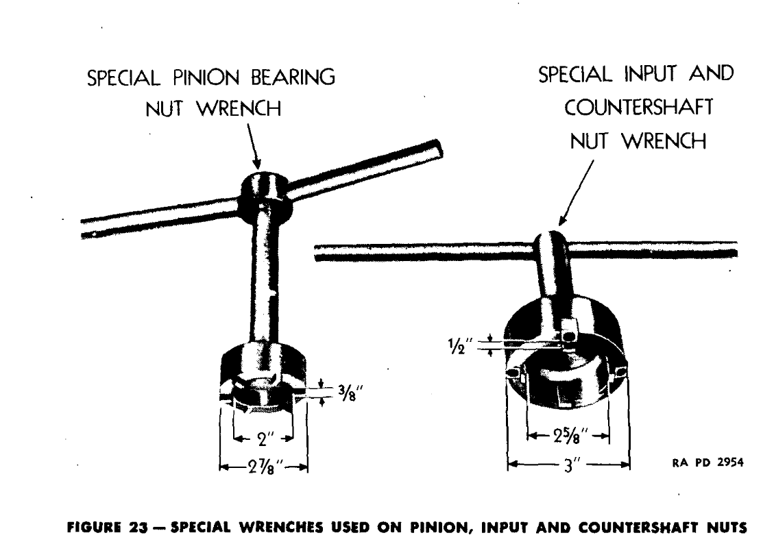
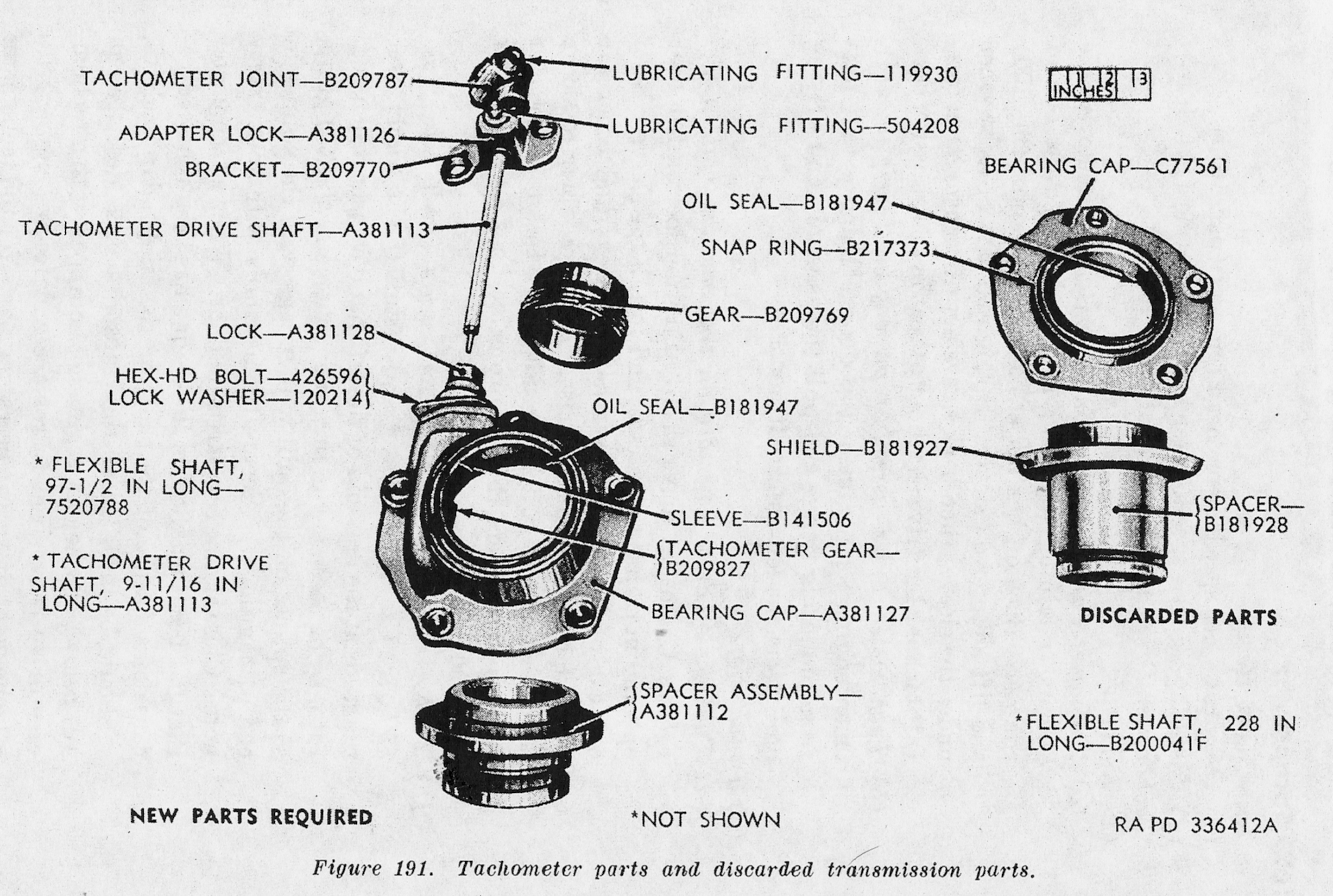
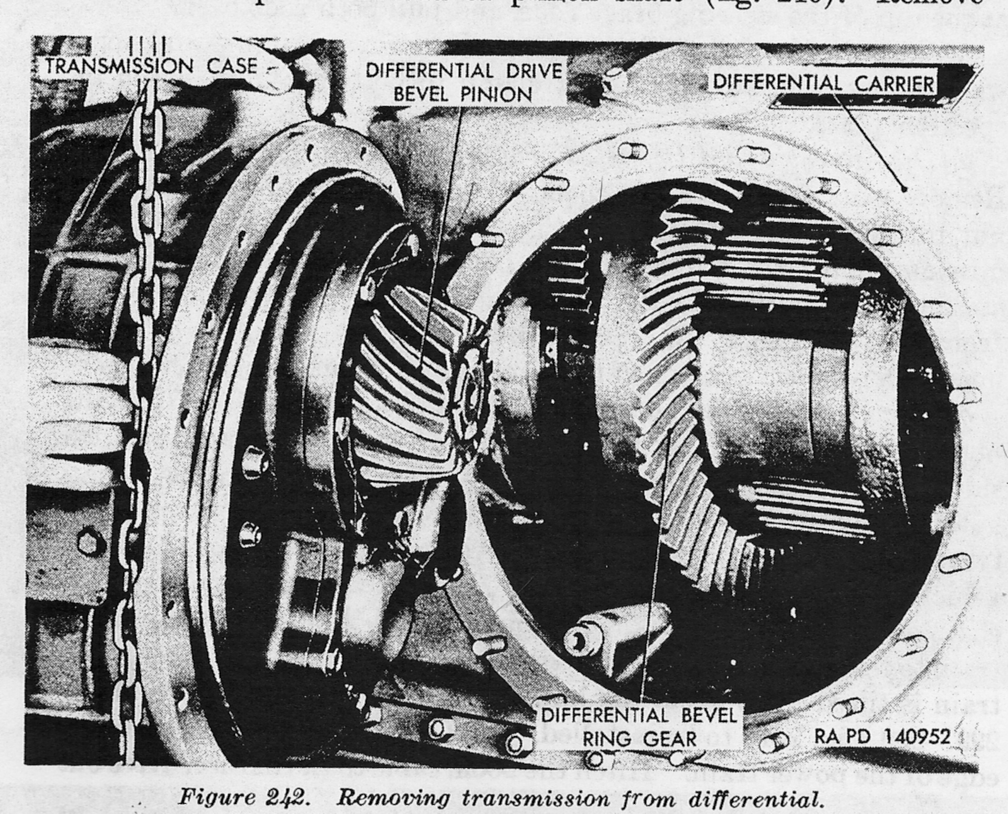
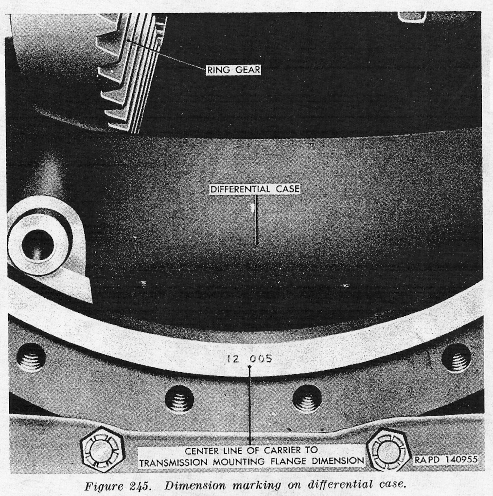
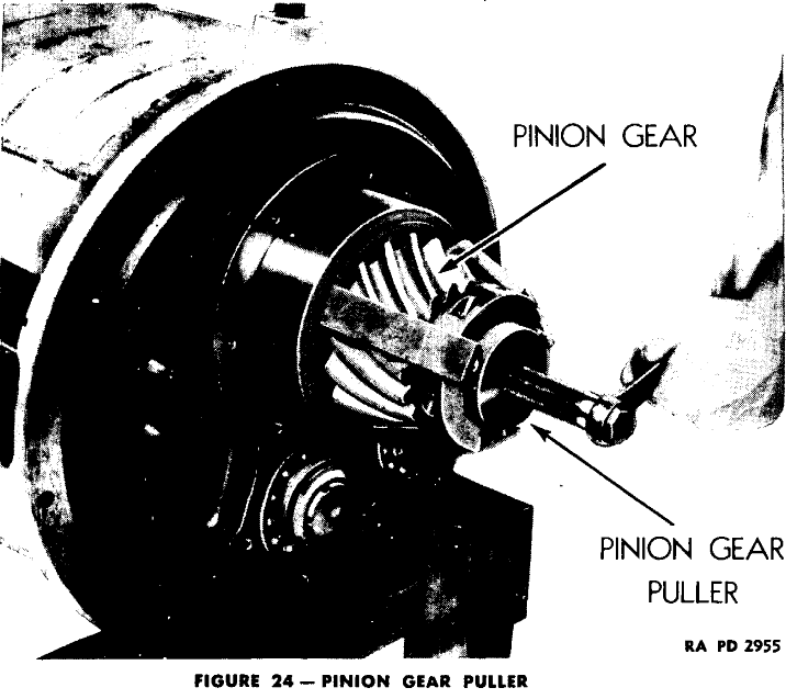
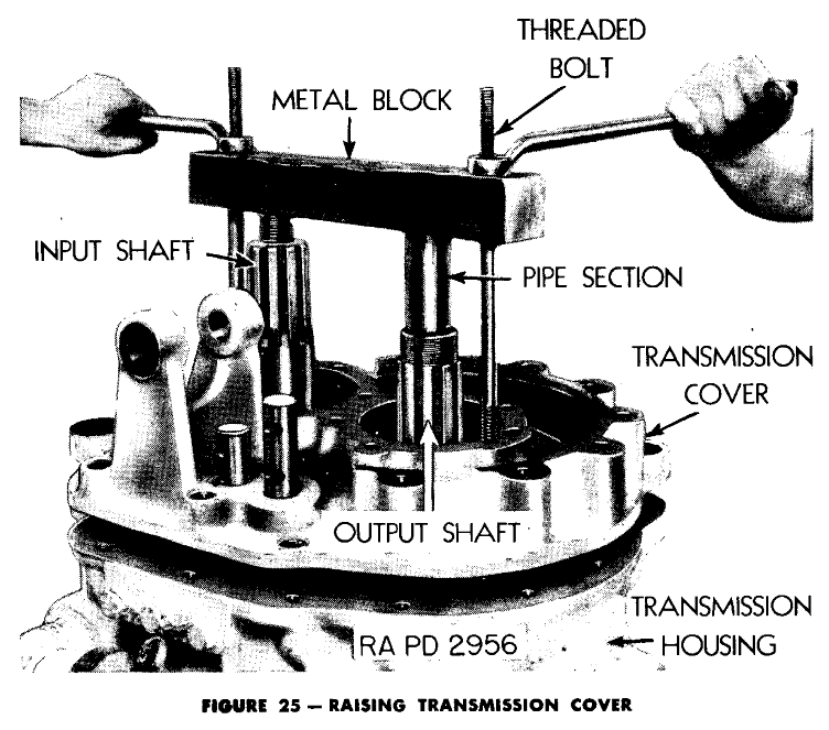
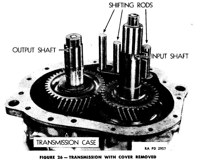
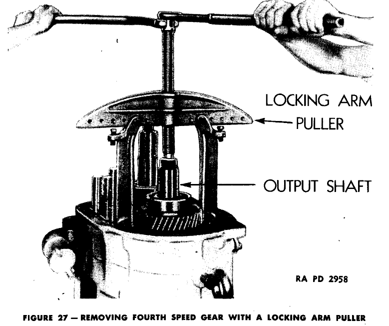
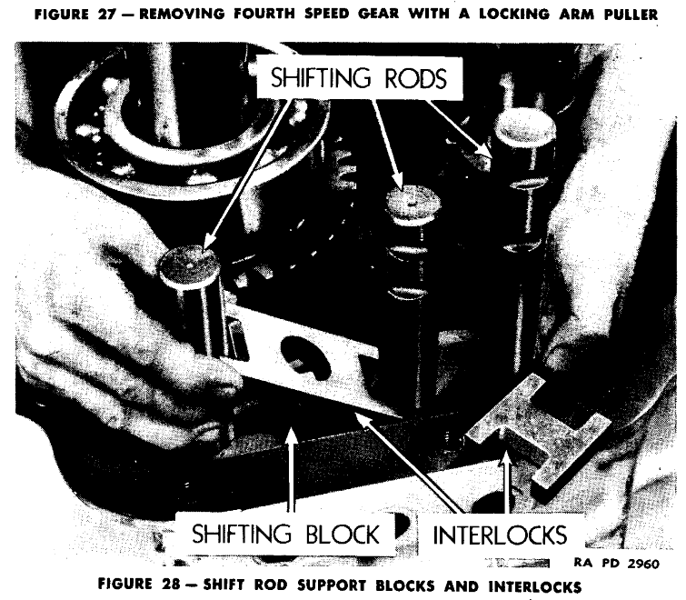
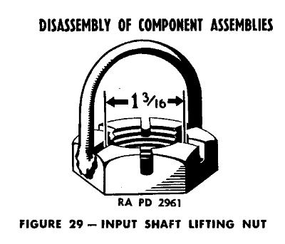
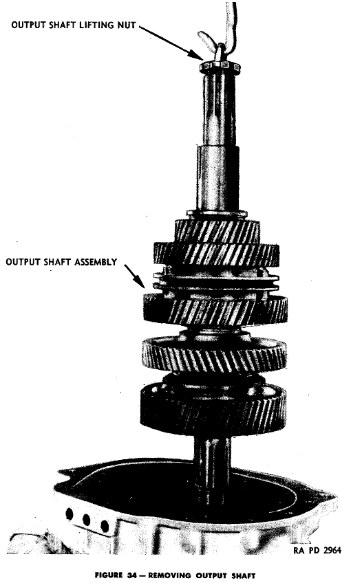
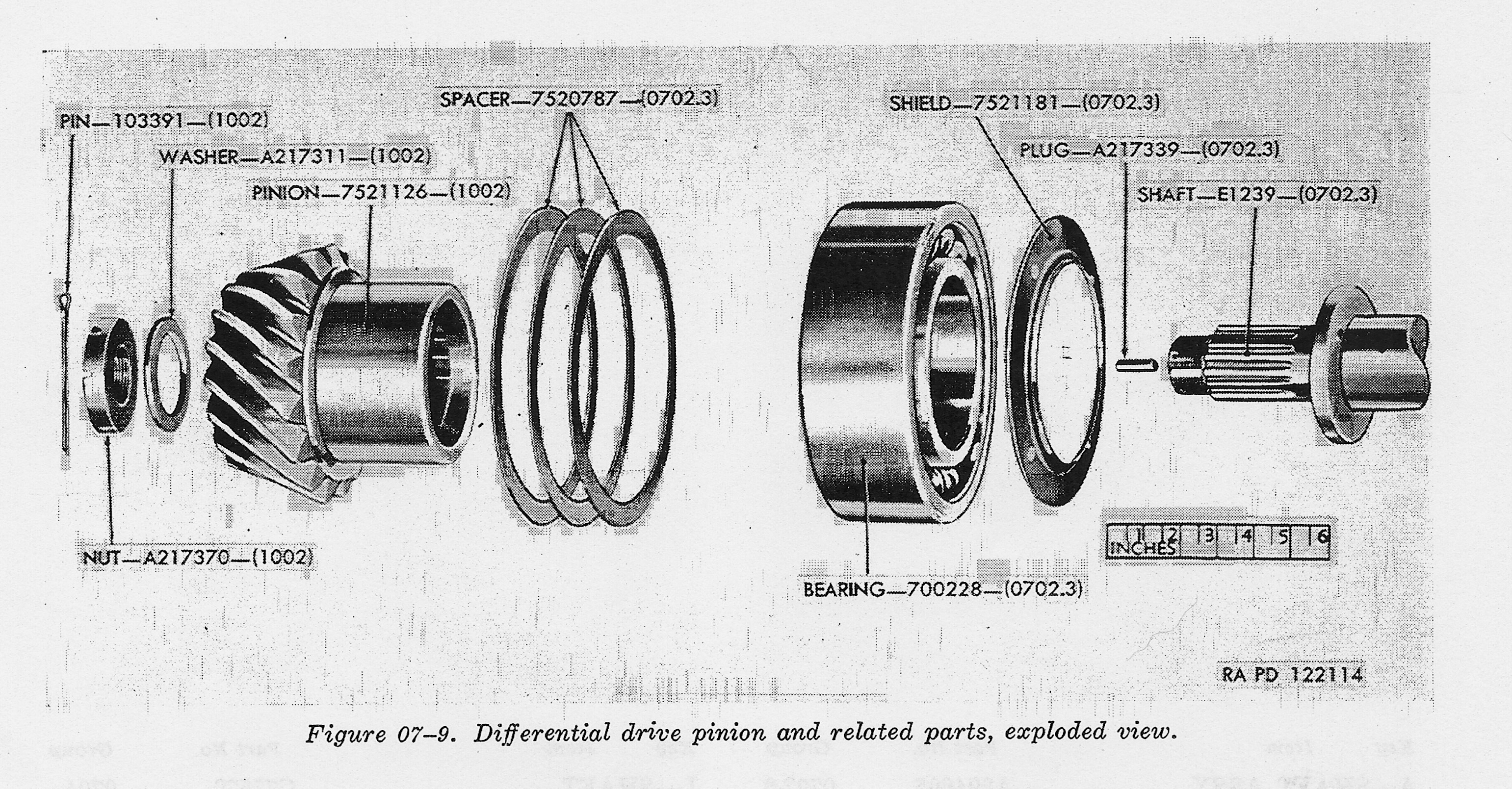
In the above images, you can see the pinion end of the Transmission, the part that plugs into the differential, and some special tools needed for transmission work.
The transmission was manufactured by Buick, Caterpillar Tractor, Chrysler Defense Arsenal, Ford Motor Company, Iowa Transmission, and Reed Roller Gear Company. Though I do not know for sure, several sources have mentioned Caterpillar as the original designer of the Transmission. The Army Tech Manuals are not very good for figuring these things out, they rarely mention the manufacturer, let along the original designer. The parts from all the manufacturers above worked with all the other manufacturers parts. In many cases the companies listed above may have shared sub contractors. One of the most interesting mysteries of Sherman, and many military products from WWII, the sub contractors are unknown. There were hundreds of little companies all over the USA that helped contribute to world war II war production, and the Sherman specifically.
The Transmission Gallery: Technical Drawings and Maintenance pictures
![]()
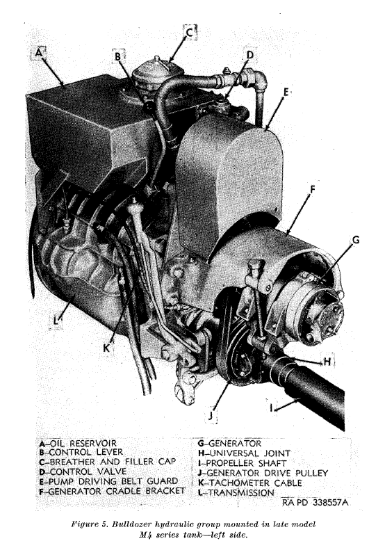
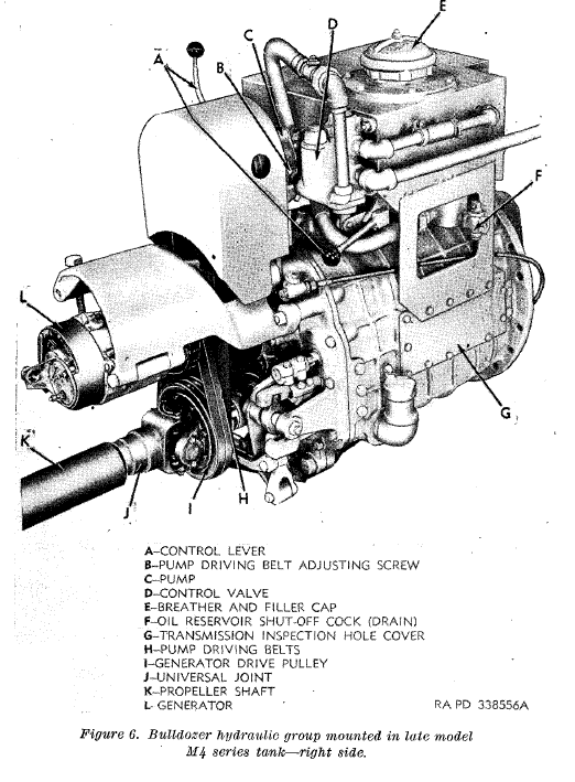
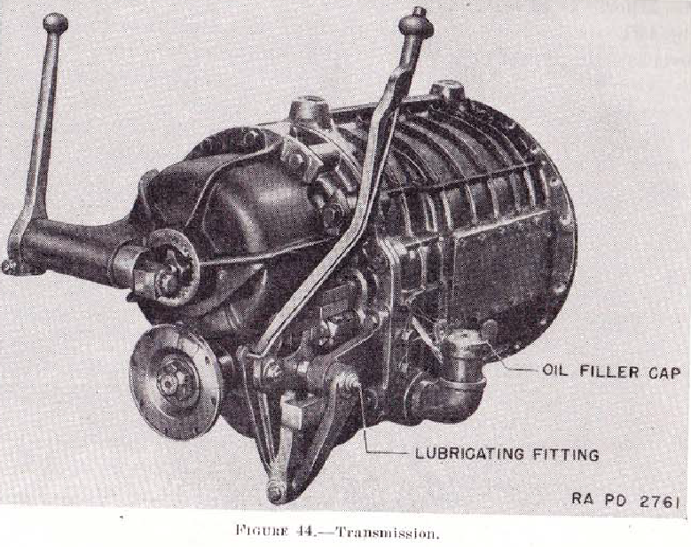
This is the rear left view of the Shermans Transmission. Not the studs around the top rear, several things could be mounted here most commonly a generator driven by a pulley on the drive shaft/propellor shaft. This is and the two mounting points on the top of the transmission would be used to mount the hydraulic pump for the M1 Dozer blade kit.
![]()
In this image you can see the transmission stripped bare with the side access plate removed. S and R are the shafts the shifter moves in and out that move the forks that change the gears.

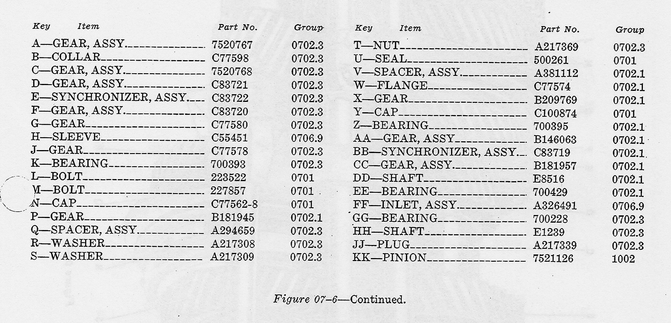
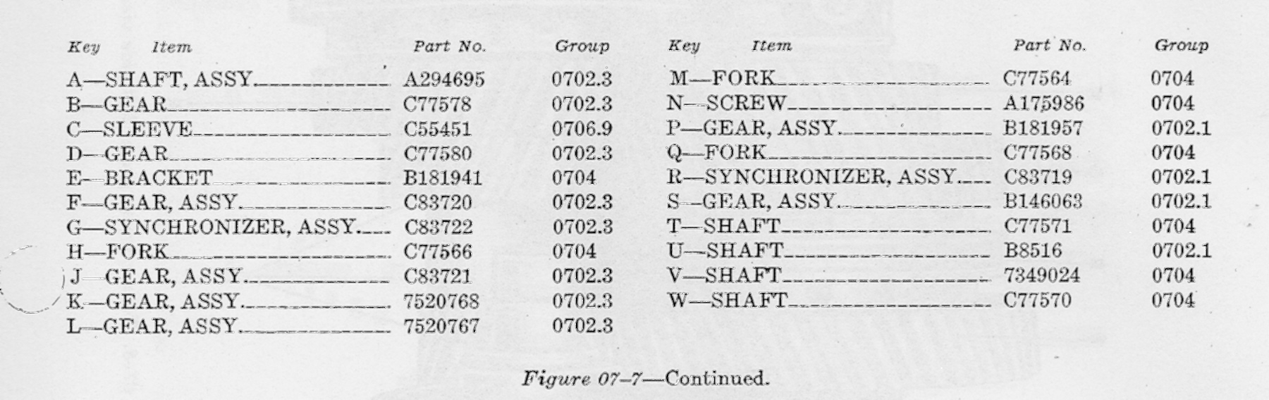
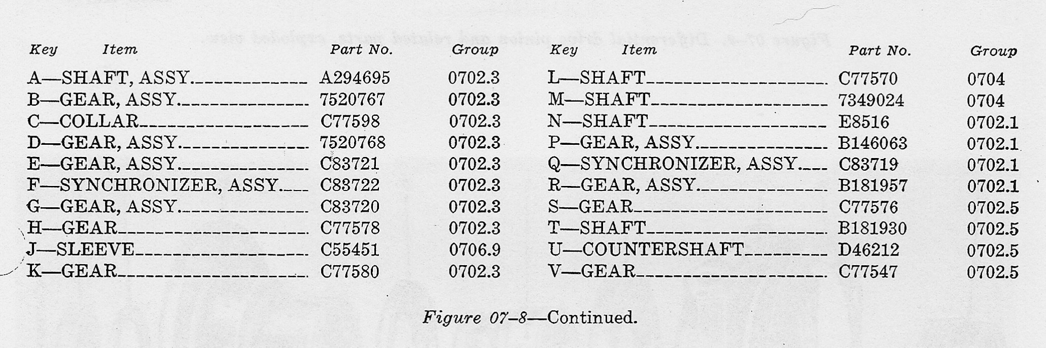
Gear Part Numbers, to help figure out the diagrams. 1st Gear 7520767, 2nd Gear C83721, 3rd Gear C83720, 4th Gear B146063, Fifth Gear B181957, Reverse 7520768
Gear Part Numbers, to help figure out the diagrams. 1st Gear 7520767, 2nd Gear C83721, 3rd Gear C83720, 4th Gear B146063, Fifth Gear B181957, Reverse 7520768
Gear Part Numbers, to help figure out the diagrams. 1st Gear 7520767, 2nd Gear C83721, 3rd Gear C83720, 4th Gear B146063, Fifth Gear B181957, Reverse 7520768
![]()
![]()
![]()
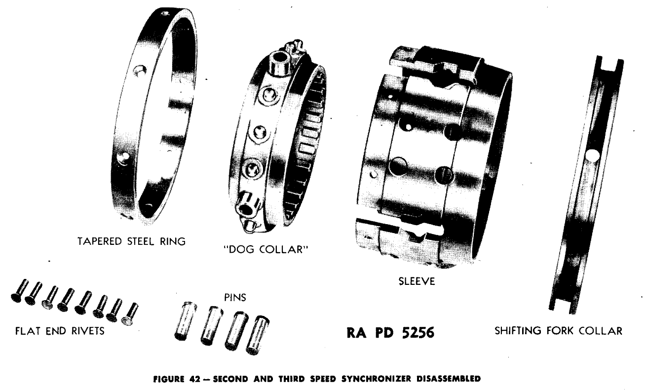
In the two images above, click for larger versions, you see the transmission syncros. These speed the gears up to the same speed so they can mesh without grinding or a lot of effort. These wear out over time. Bad driving habits wear them out faster. The shifter is not a handrest!
![]()
![]()
These are the idler shafts, exploded view, I think we all know what Idler shafts do right? (If you know please share, my transmission mechanical knowledge has been stretched to the limits here!)

![]()
![]()
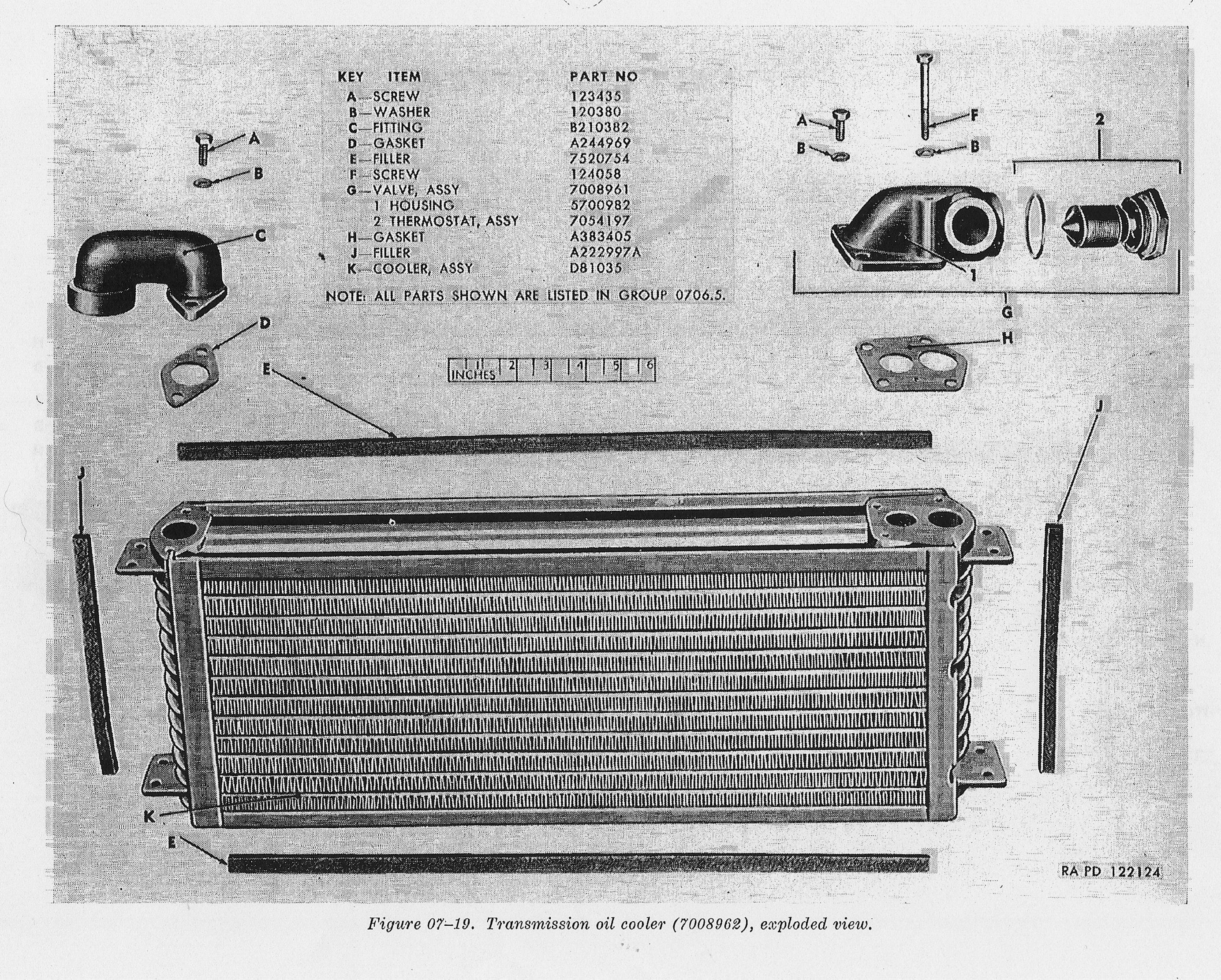
In these four images, we have the shafts used to shift the transmission gears, the oil pump used to circulate oil in the tranny, and the oil cooler that it gets pumped through. The final image shows the plumbing and location of the oil cooler in the fighting compartment.
Sources: Ord 9 SNL G-205, TM9-7018, TM9-754
![]()