The Sherman Differential: The most complicated part of the Powertrain!
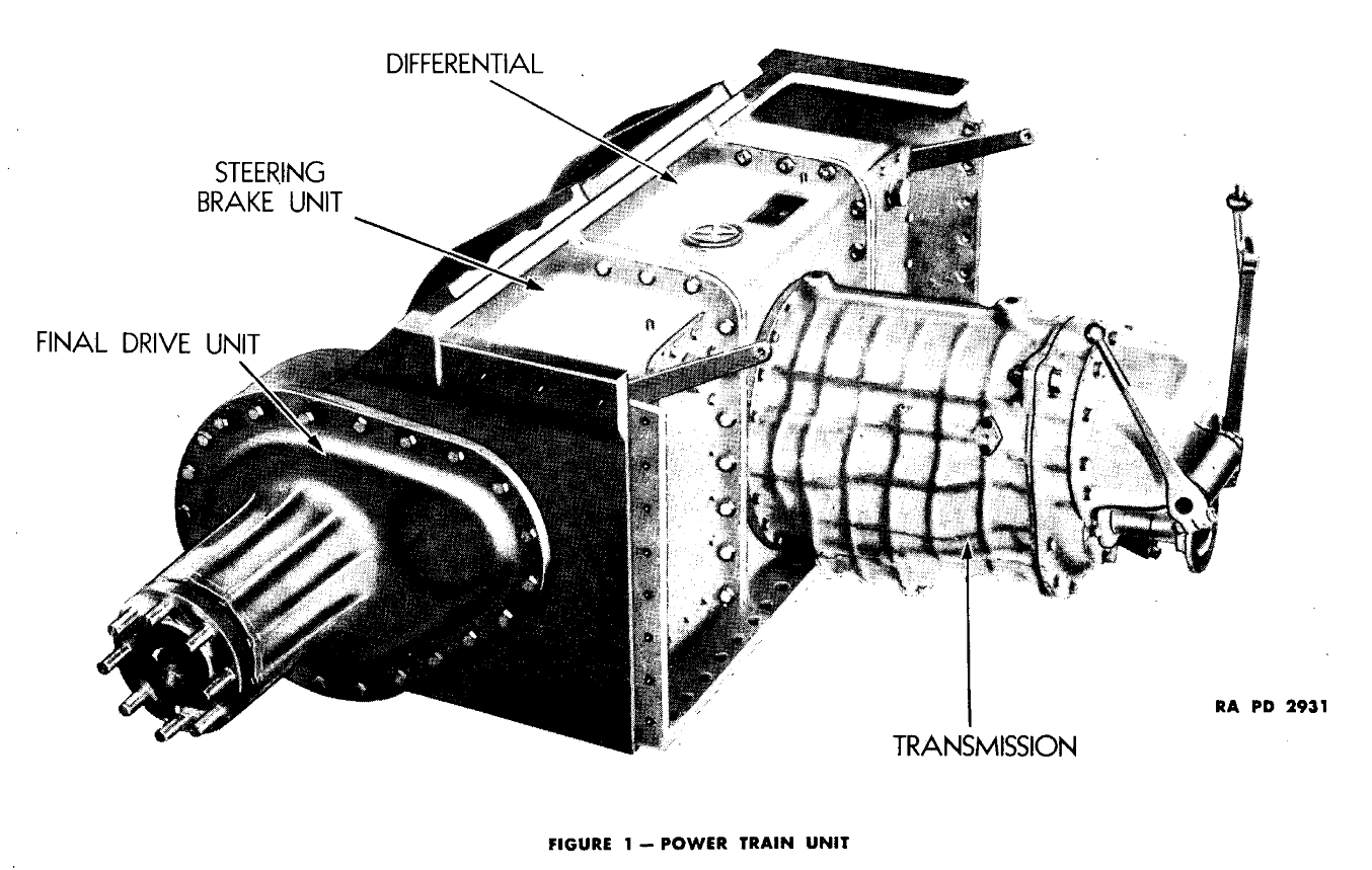
The differential takes the power being sent from the motor, through the transmission, and transfers it to the final drivers, that turn the sprockets and move the tank. The is of the compensating type, meaning it allows one track to move faster or slower than the other to compensate for irregularities in the ground and corners and also provides for steering.
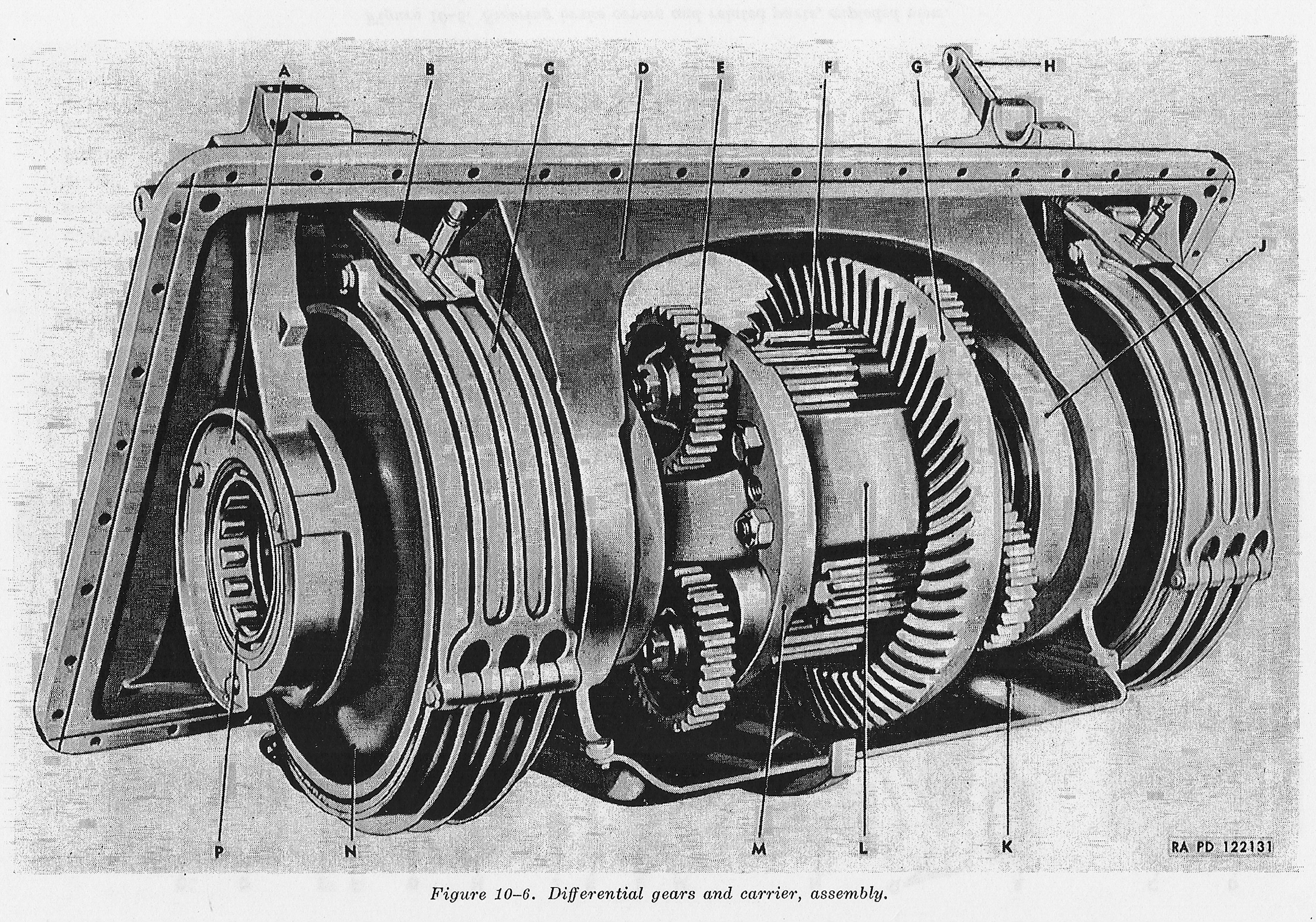
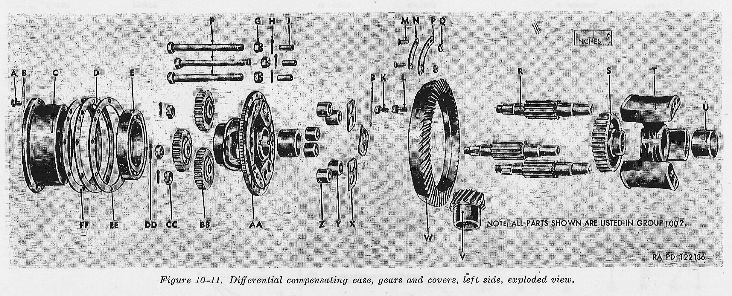
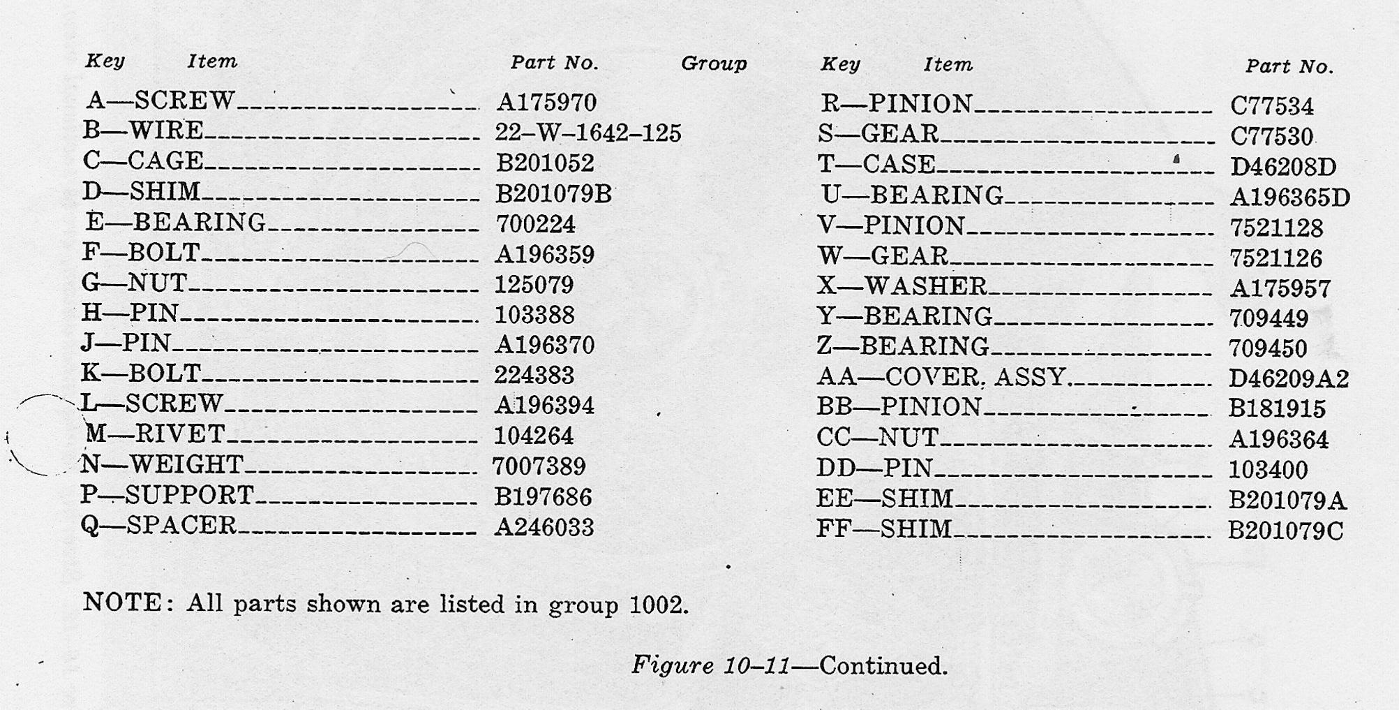
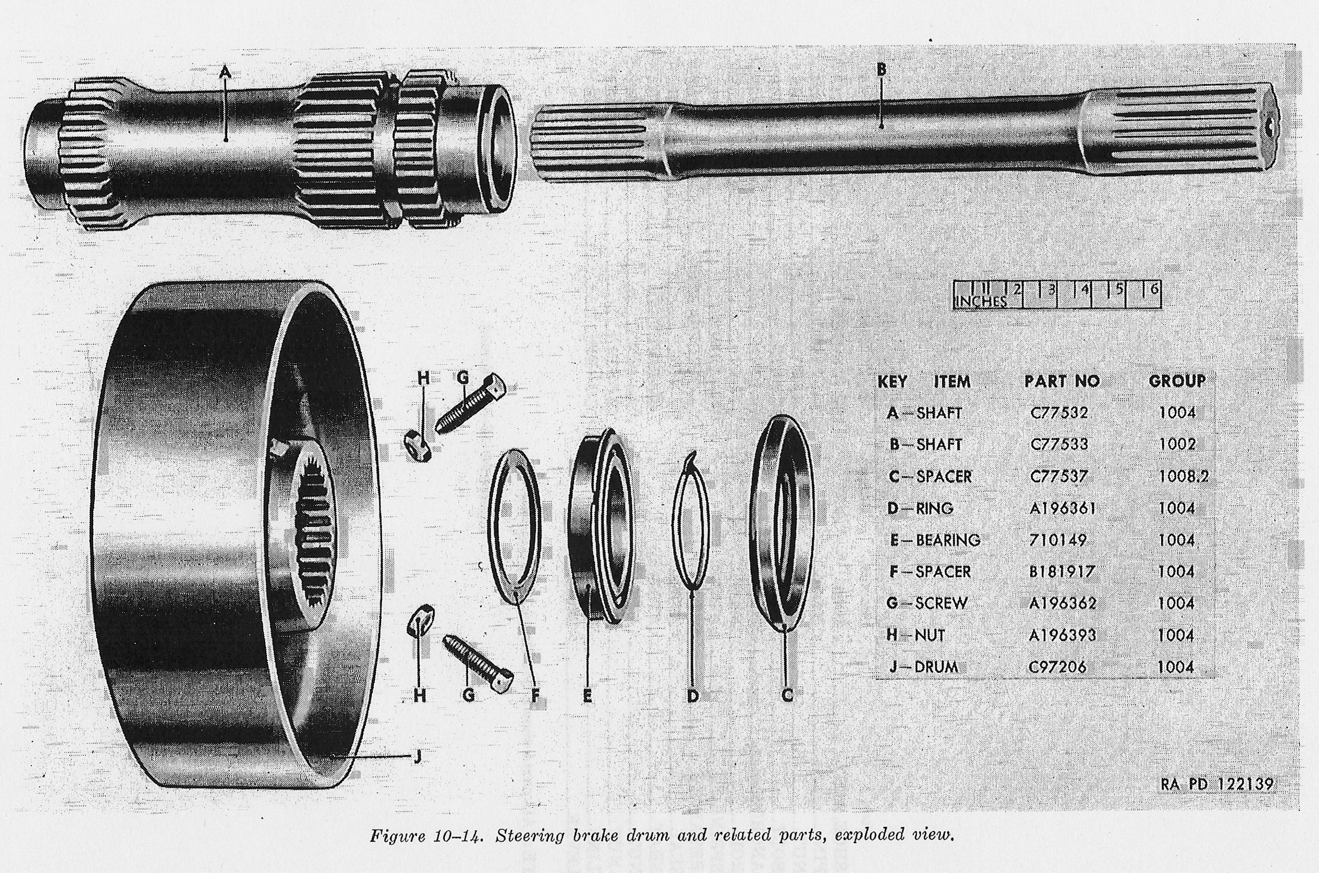
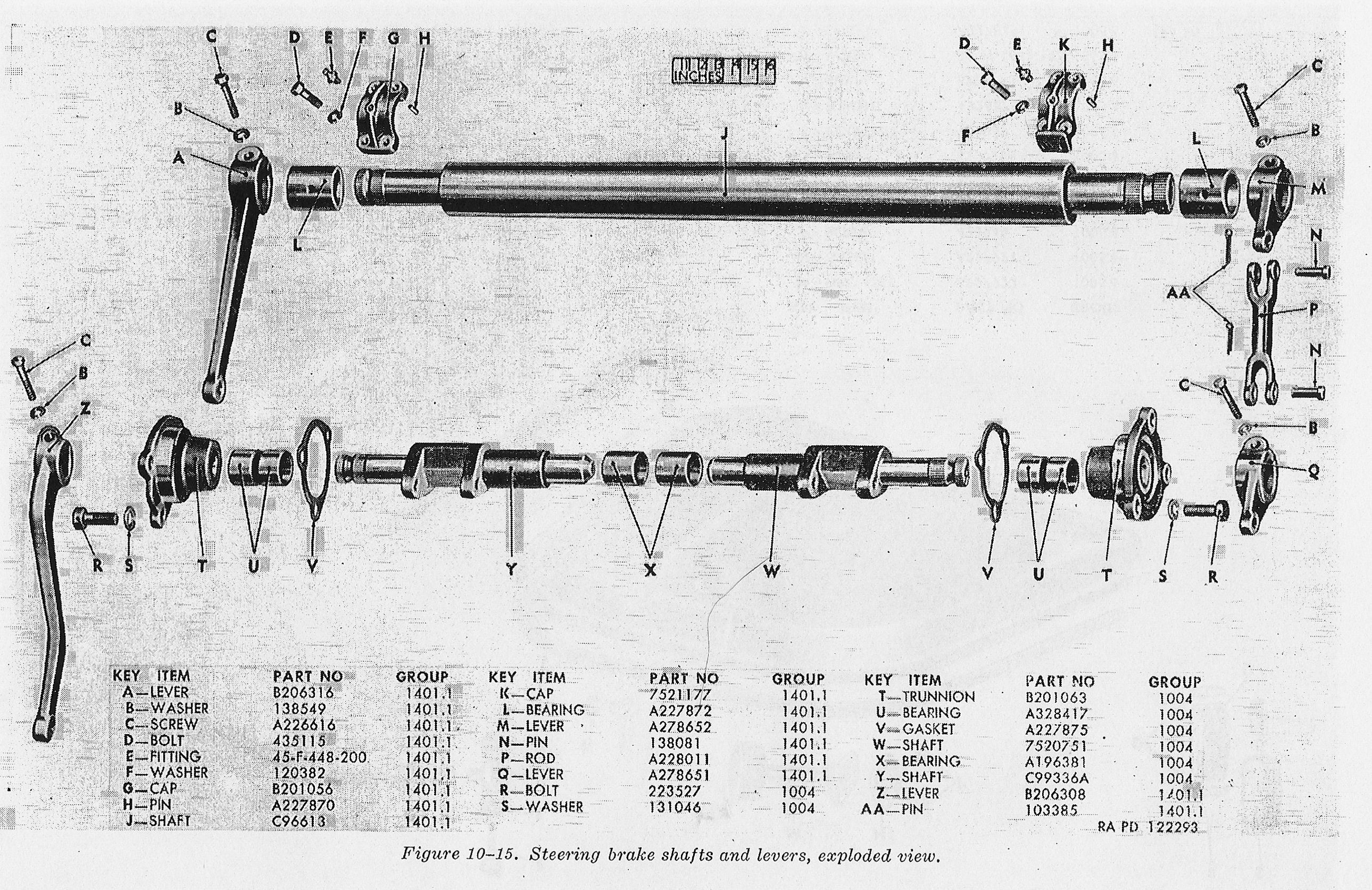
That means the power from the transmission is sent through the main bevel gear, the bevel gear operates one set of gears and a compensating shaft on each side for steering and braking purposes and another set of gears and compensating drive shaft on each side for driving purposes. Each compensating shaft carries a steering brake drum.
When a steering brake drum lever is pulled, it tightens the brake band and slows or stops the brake drum on its particular side. This slowing or stopping of the brake drum and its compensating shaft on the side the braking lever was pulled on, causing the tank to turn that way. The sharpness of the turn depended on how far back the lever was pulled. I If both levers were pulled in unison, the tank would slow or stop without turning.
This type of gear train construction also relieves the driving gears and shafts of extra stresses imposed by the steering system. Power leaves the differential through the two compensating shafts. This made for a robust and reliable differential.
The Sherman tank on all models but the M4A3E2 Jumbo had a Bevel Gear ratio of 3:53 to 1, steering ratio of 1.5515 to 1, and a final drive ratio of 2.84 to 1. The Jumbo was the same except its bevel gear or final drive ratio was 3.36 to 1, slight reducing its top speed, but giving it a little more grunt to move the extra armor.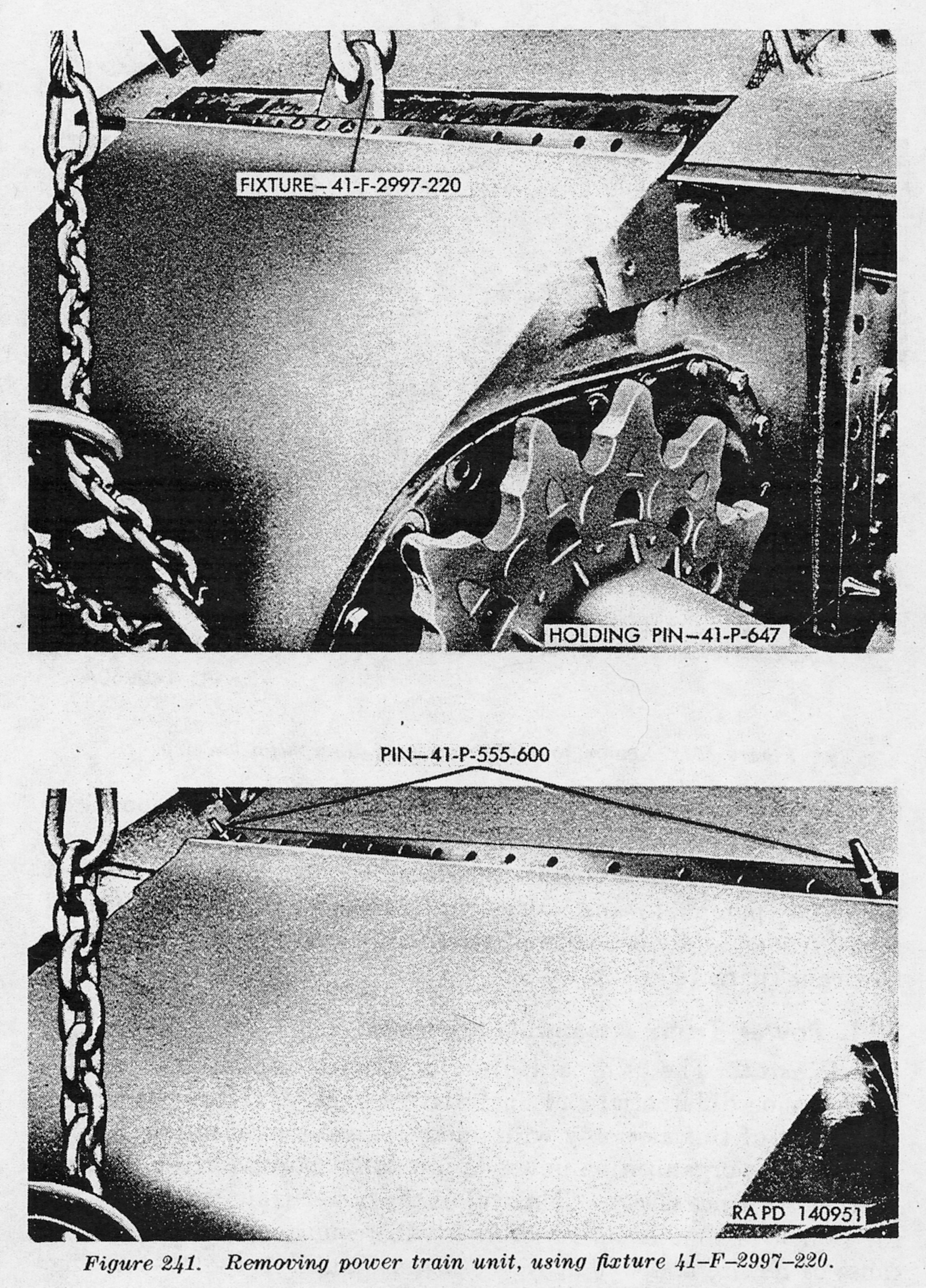
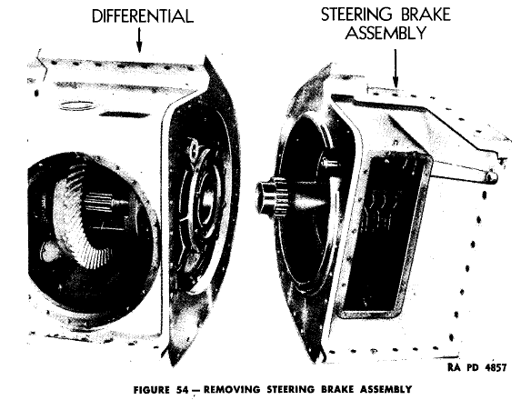
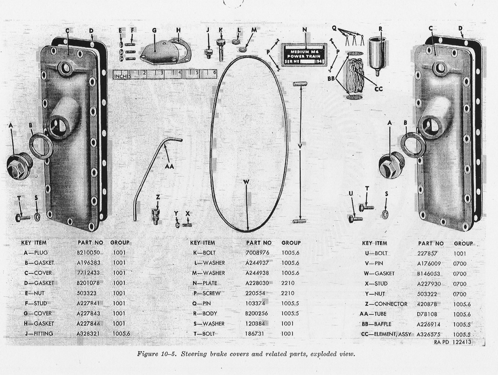
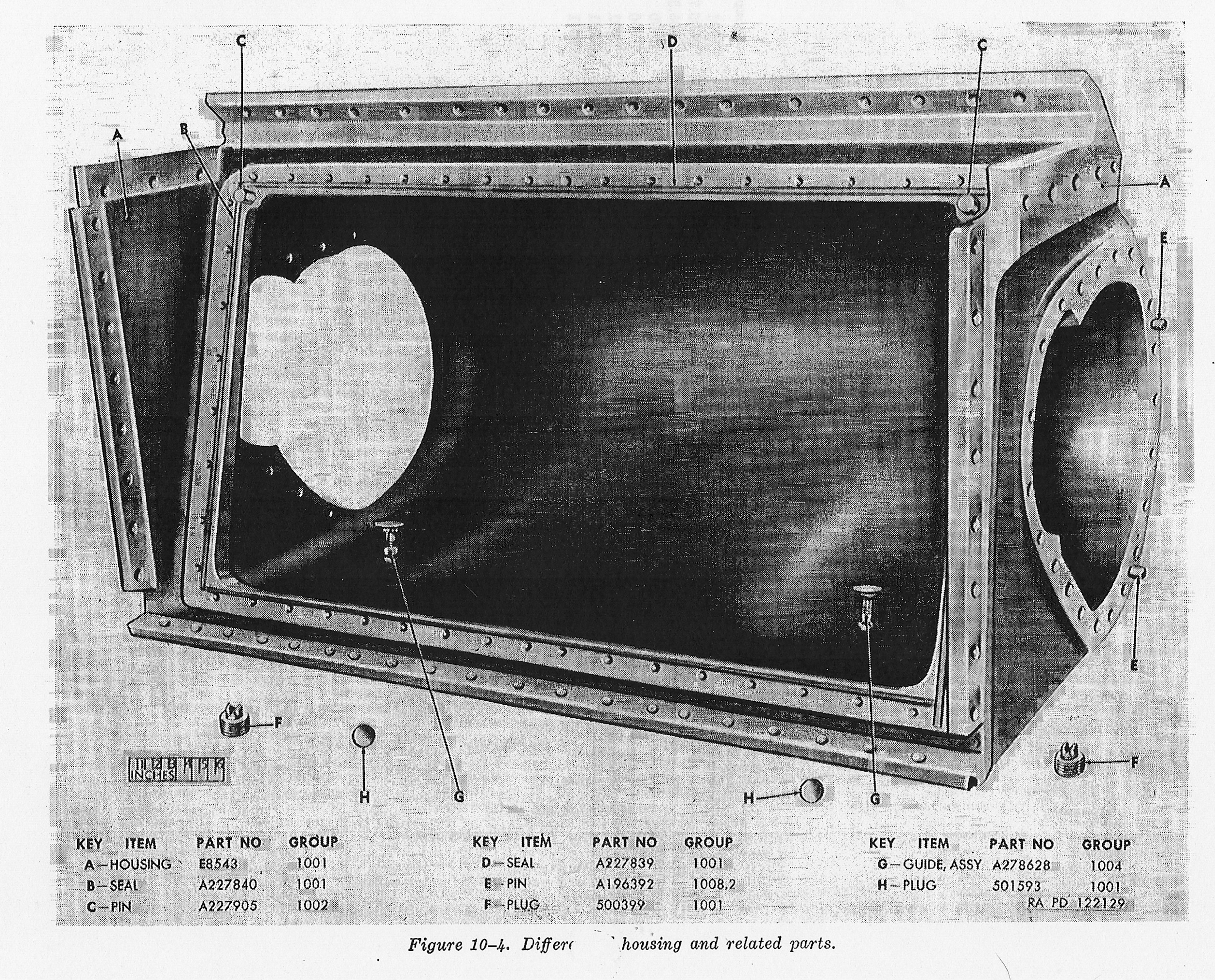
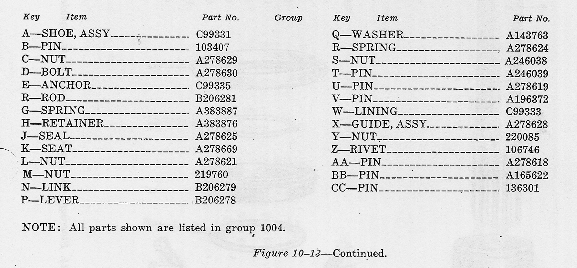
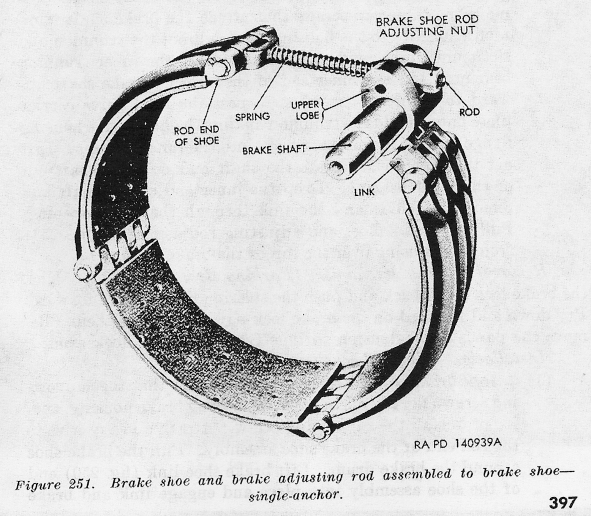
The description for how the differential works, comes from, almost word for word, TM9-1750. I really wish I had the version for the cast one piece powertrain, but I do have a ton of very nice parts break down images of it. The actual gear train didn’t change much between the models from what I can tell. But the casing did, and when they switched the the single casting model, they also upgraded the braking system from a one anchor, to two anchor system, see illustrations below for more detail, but the new brake modifications applied more clamping force making the Sherman easier to steer. I do not know if the improved two anchor system can be retrofitted to the older three piece bolt together differentials.
Much like the transmission, other than serving the fluids and the brakes, including adjusting them and replacing the pads, it anything inside needed work, the whole thing was removed and swapped with a new or salvaged powertrain.
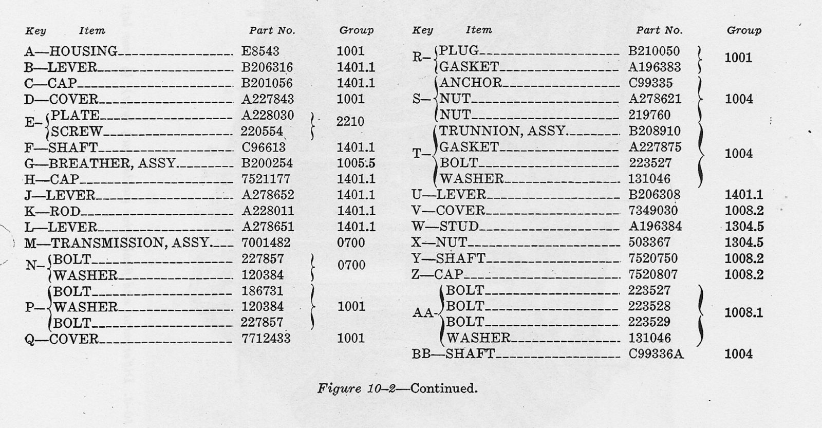
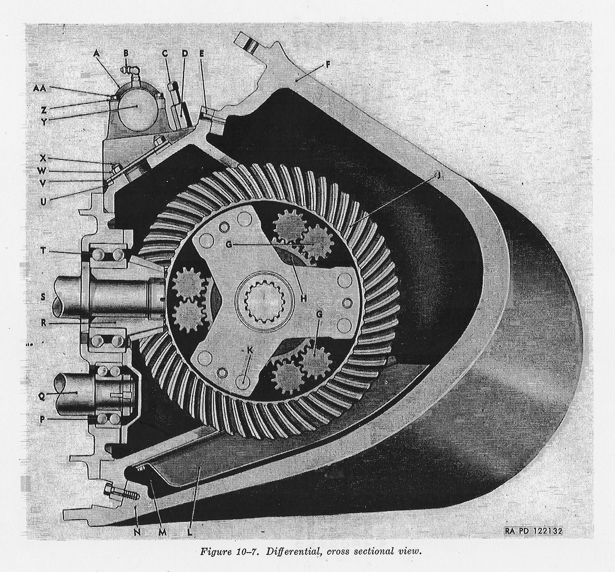
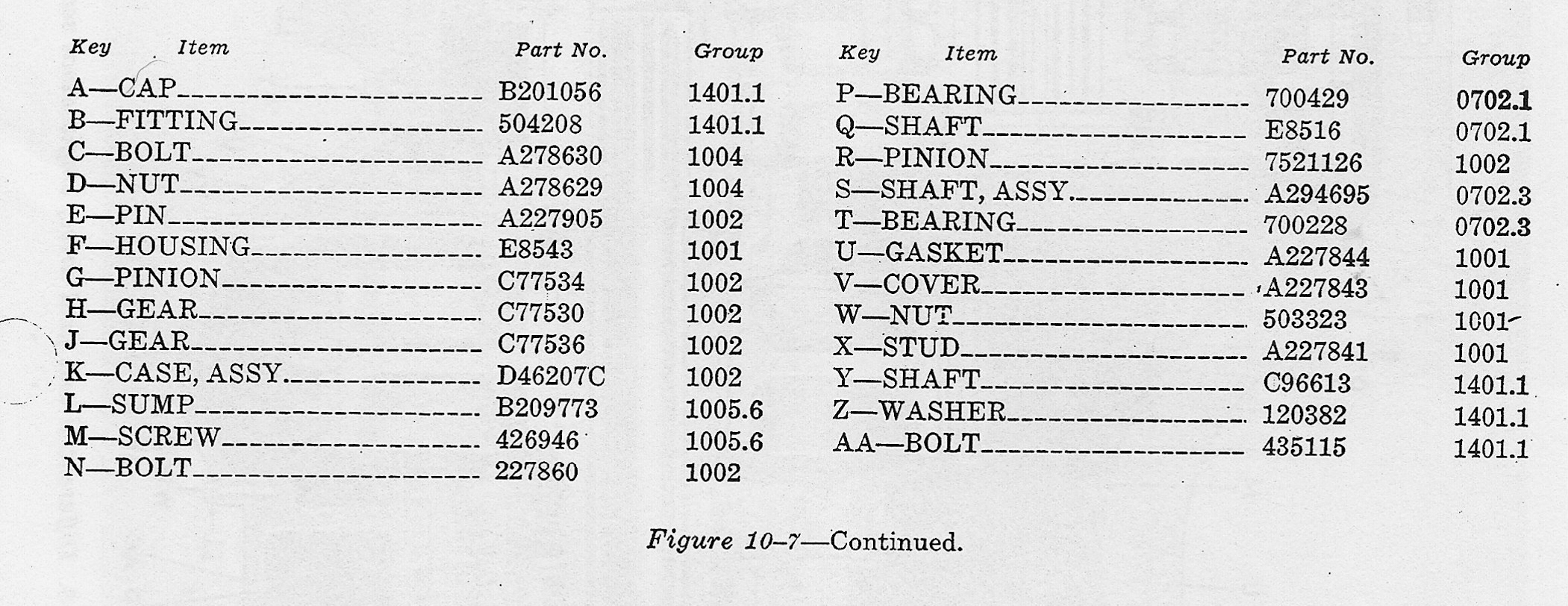
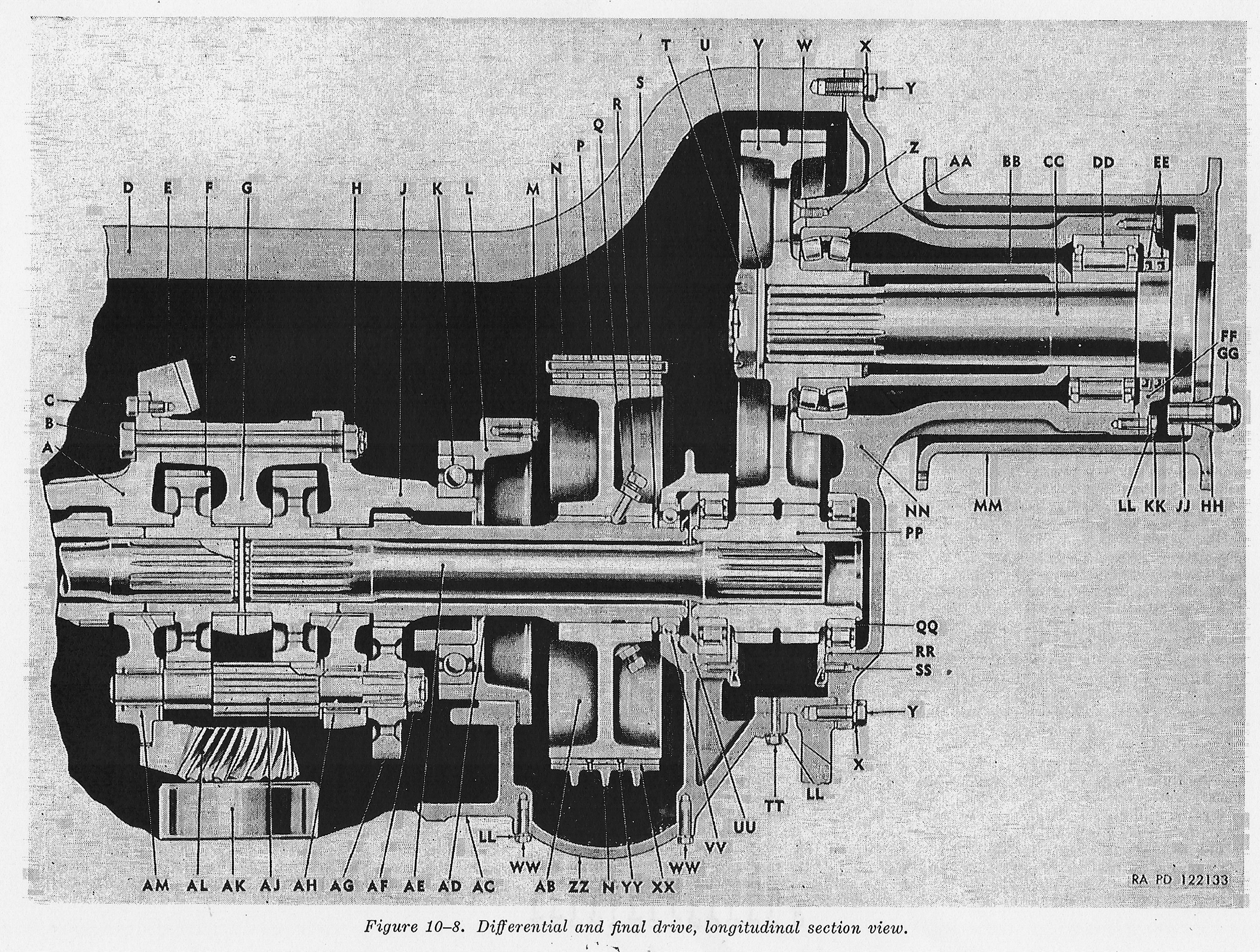
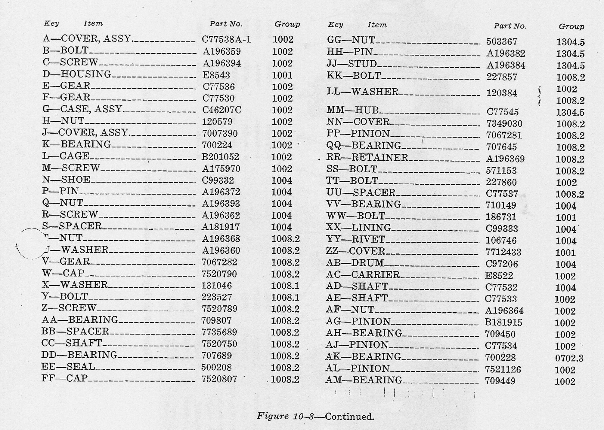
Click the above images for larger, but not much better image, of the early style three piece differential, and the differential partially disassembled.
The Powertrain Gallery: Gears, pictures of Gears, lots of gears…


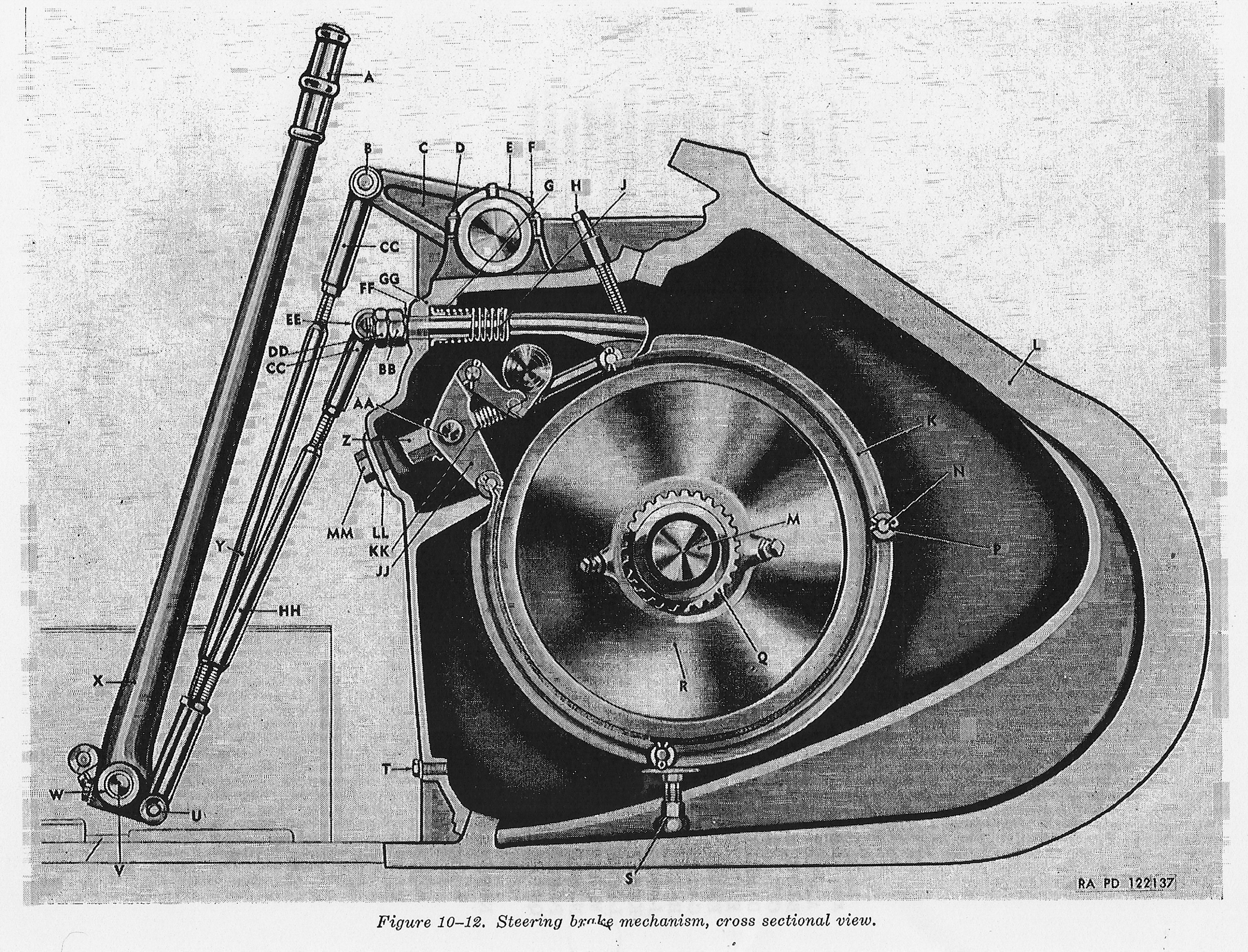
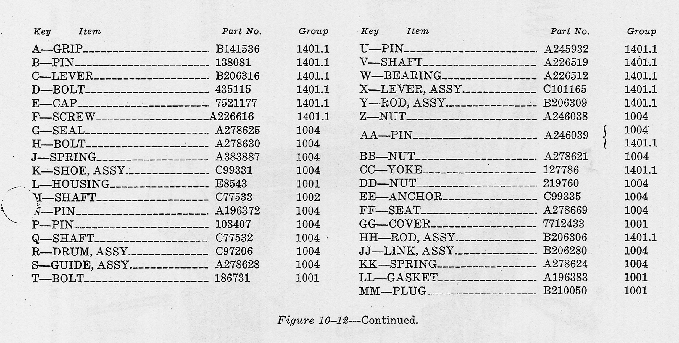


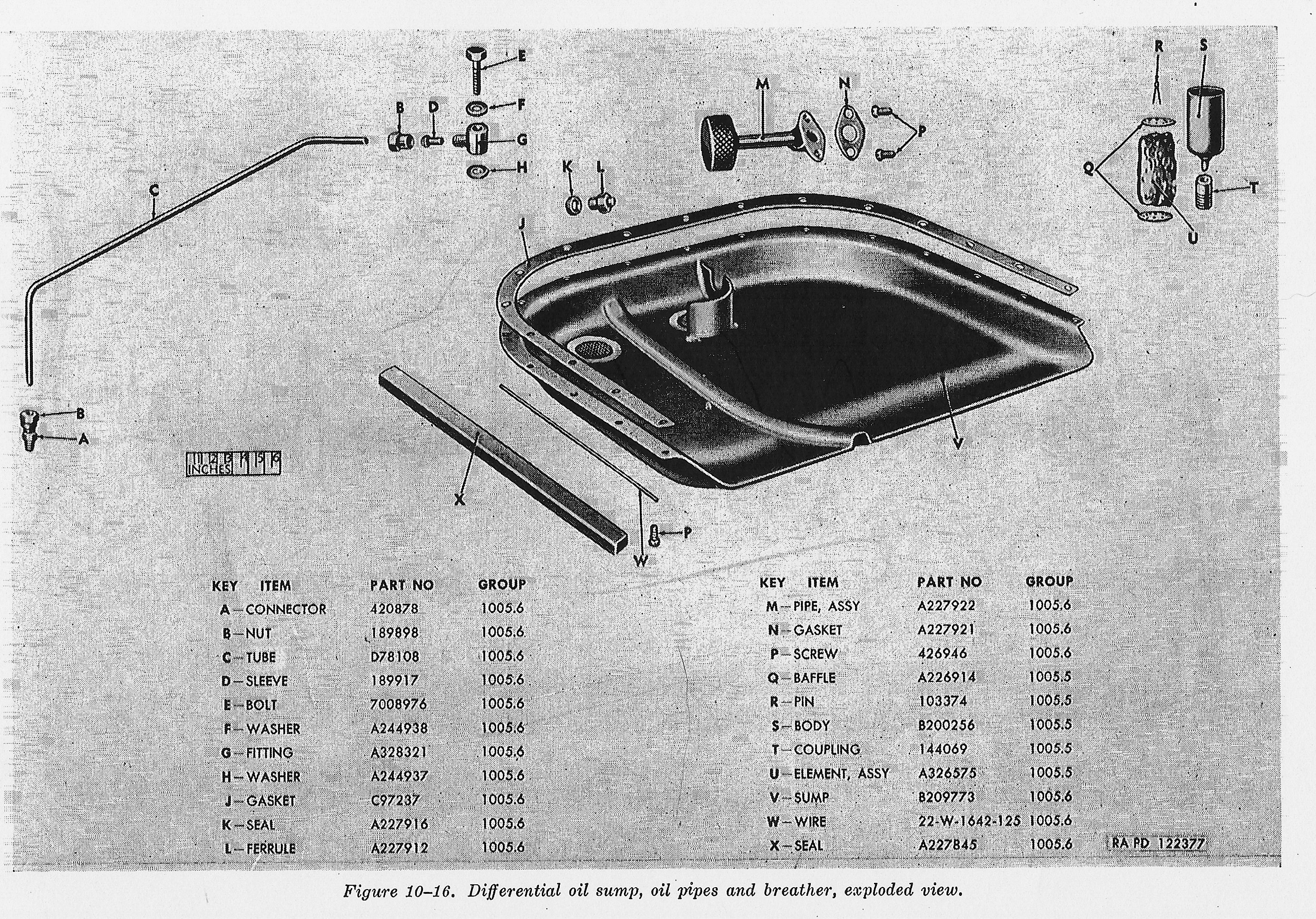
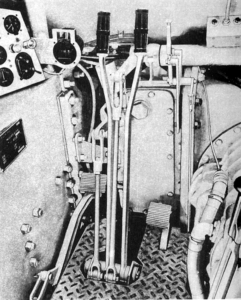
In these images you can get a nice look at the steering brake linkage, and the oil pan for the differential.