Sherman Tank Fuel Systems: The Complete fuel Systems for each Sherman model, eventually.
I have good manuals for the A57, Ford GAA and GM 6046, but do not have a good manual for the R975, at least one installed in a Sherman tank. I do have one for an SPG, but the fuel tanks are very different. I’m sure I’ll find TM9-731AA someday even if I have to order it from a company in France! For now, the wife is not convinced this is a good place to spend money, but I may be able to convince her in the future.
One interesting aspect I have discovered so far by going through the parts catalog is the fuel system uses the same parts as much as possible across Sherman models and motor types. This shouldn’t surprise me, but it did a little, I suspect I will find this across the board.
The Ford GAA fuel system for the M4A3, M36B1, AND M10A1 vehicles.
The Fuel system in the Ford GAA equipped vehicles are all pretty similar, but for now, this will focus on the M4A3 75 and 76 tank hulls, and this would include the M36B2. Even these tanks have a slightly different fuel tank layout.
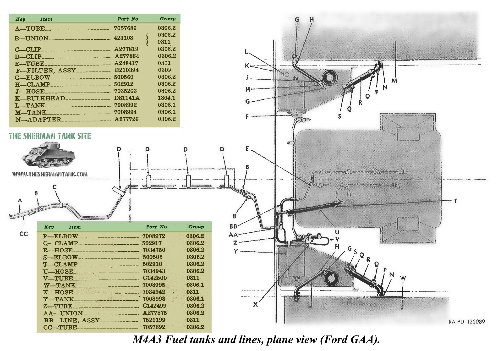
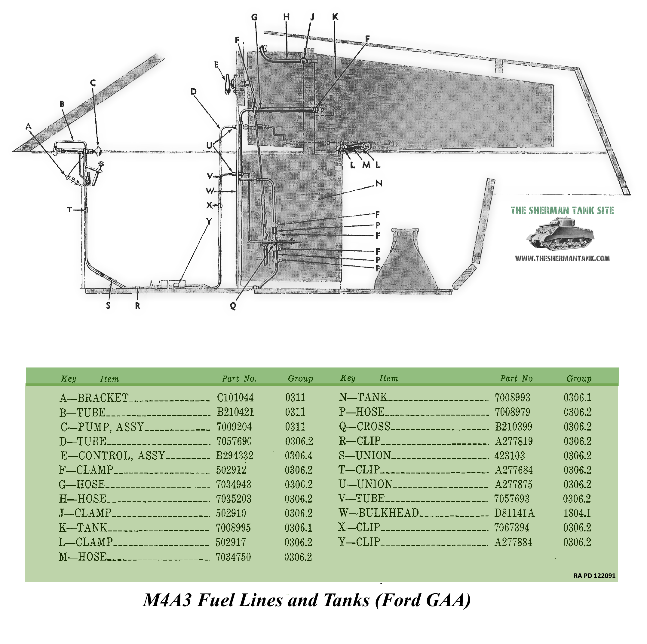
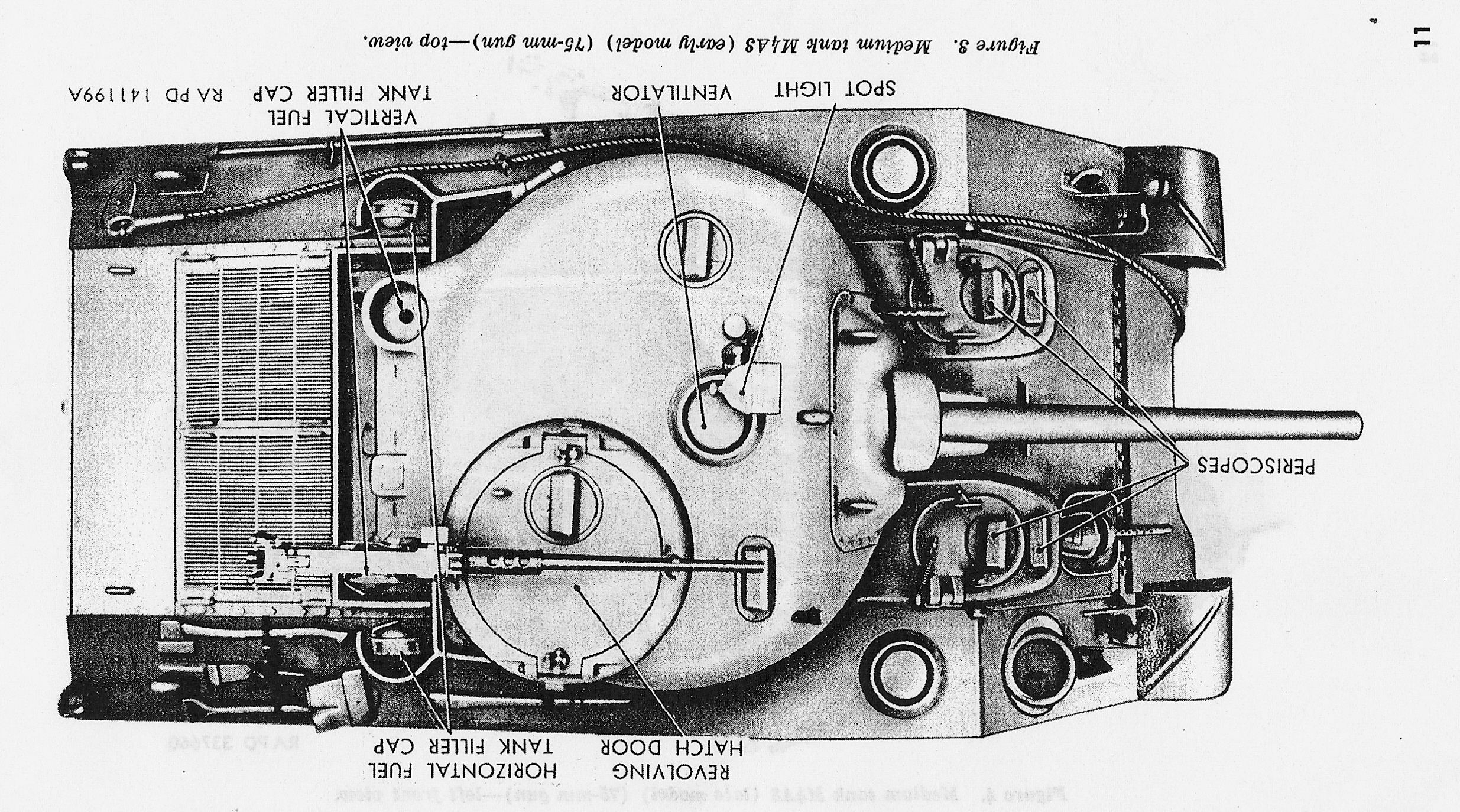
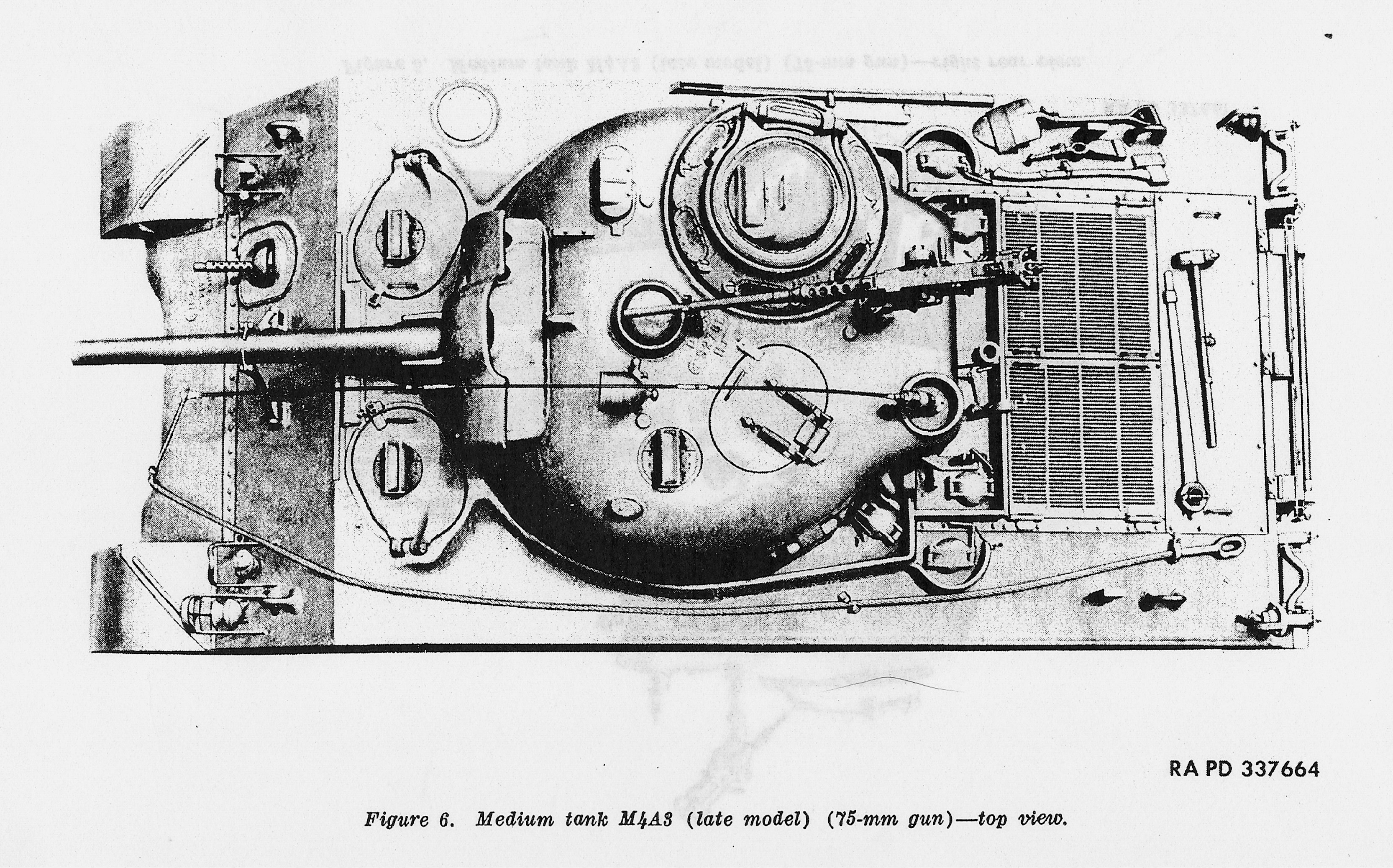
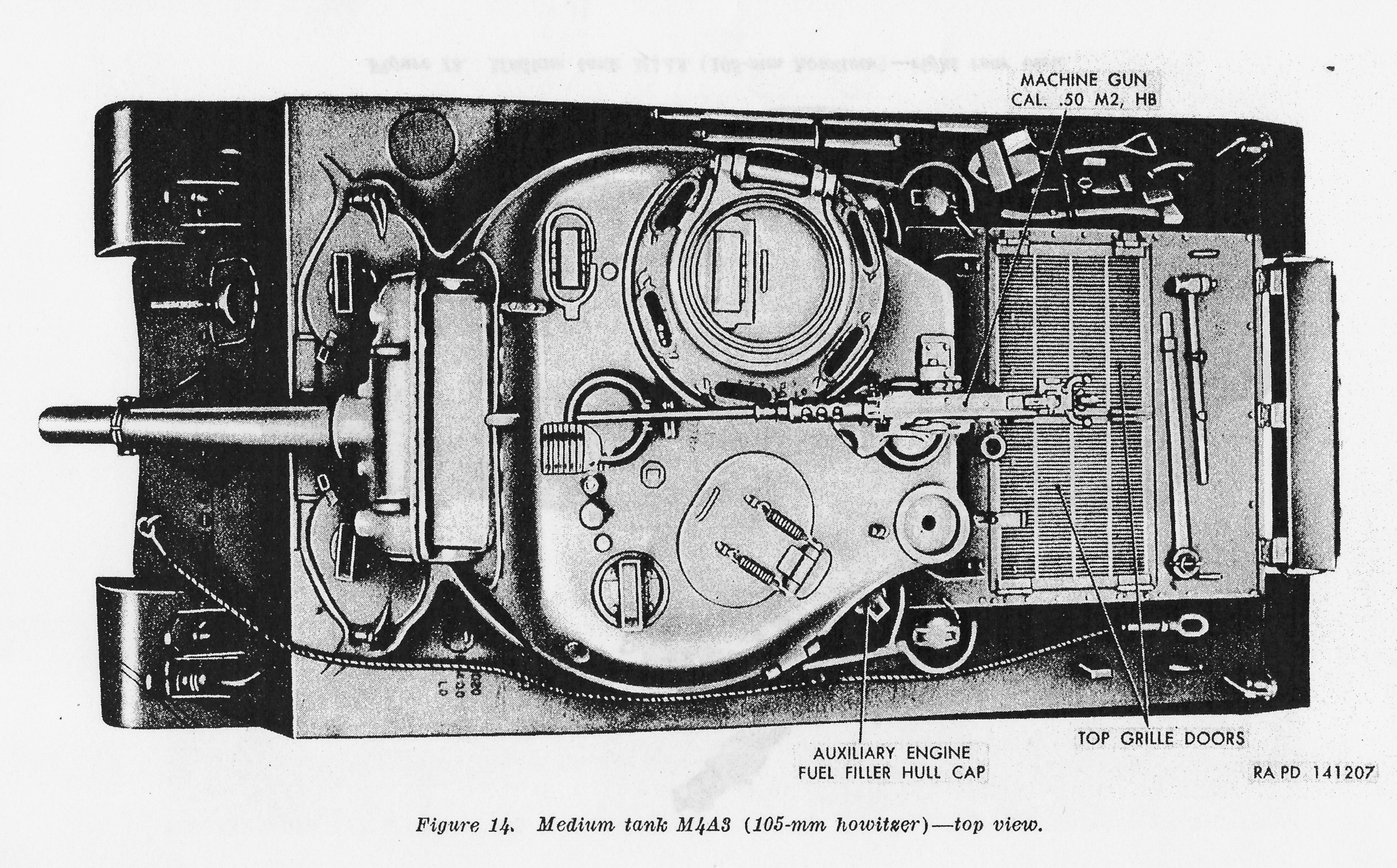
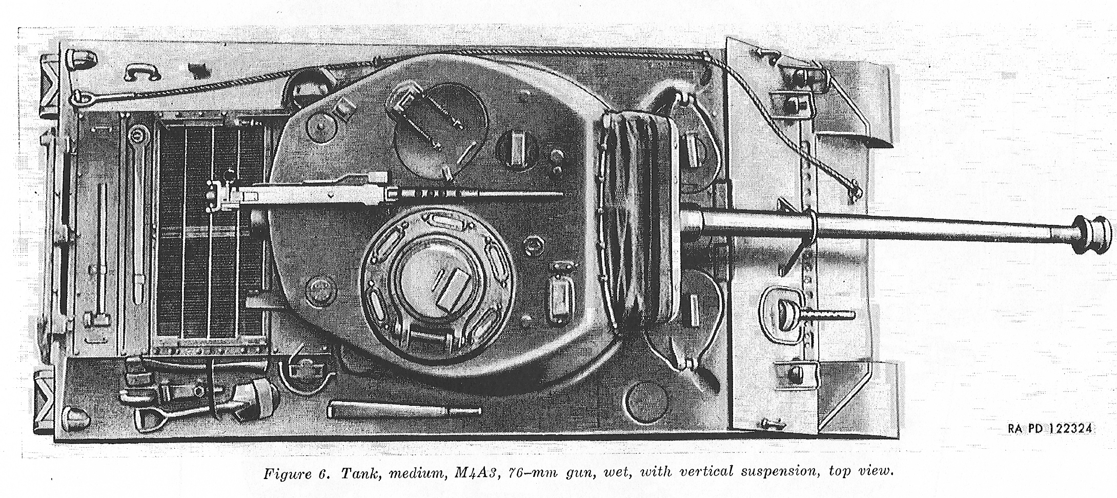
These images show the layout of the fuel tanks in the M4A3, it also shows the routing of the fuel lines and gives all the part numbers for the items shown.
By today’s standards, the fuel system on the M4A3 is very simple. It has a lot in common with automotive systems of the time, and this technology didn’t change much all the way up into the 80s when fuel injection started to become more common on gas-powered US automobiles. Anyone who’s ever worked on a carbureted vehicle wouldn’t be lost working on the M4A3 Sherman.
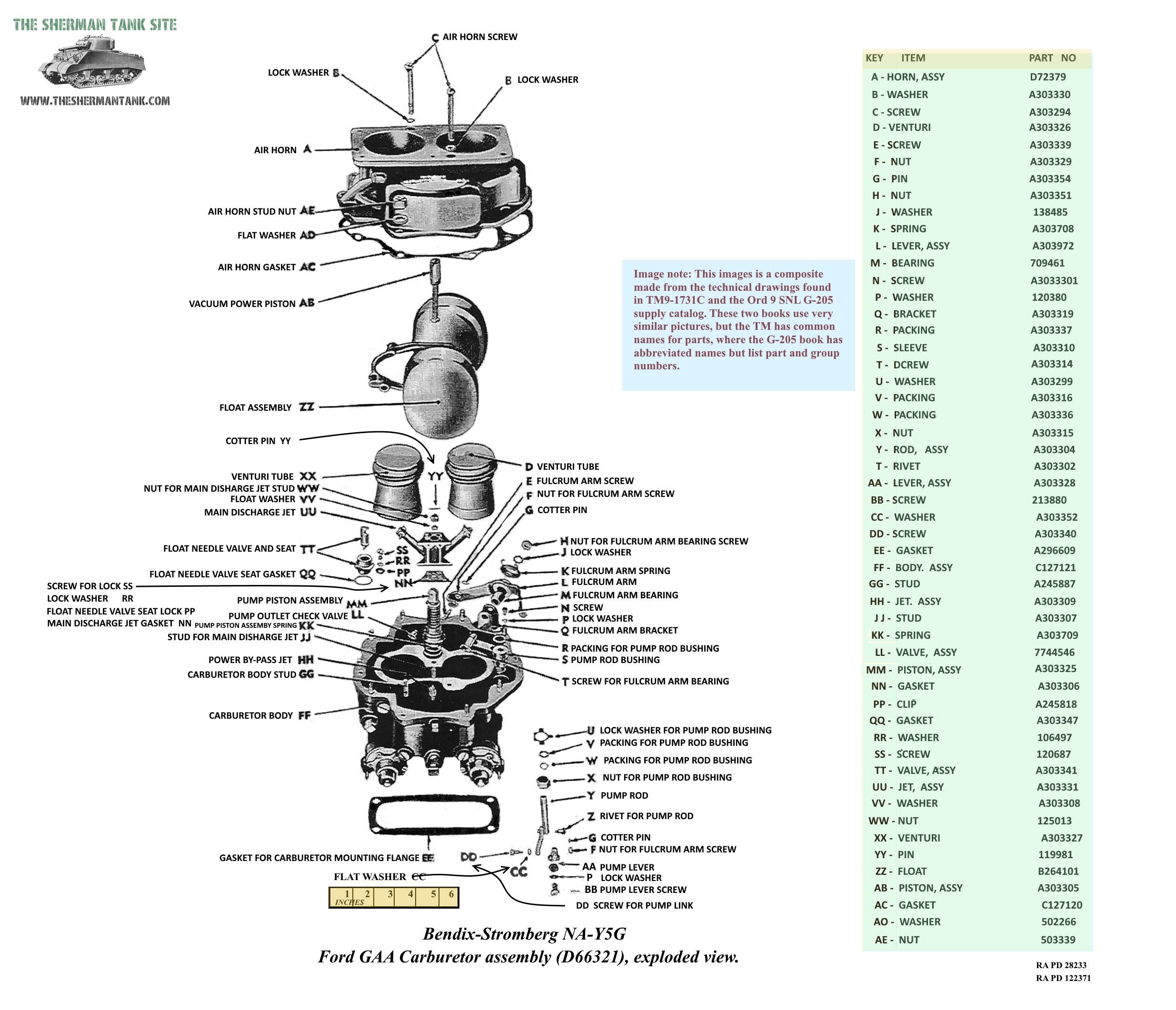
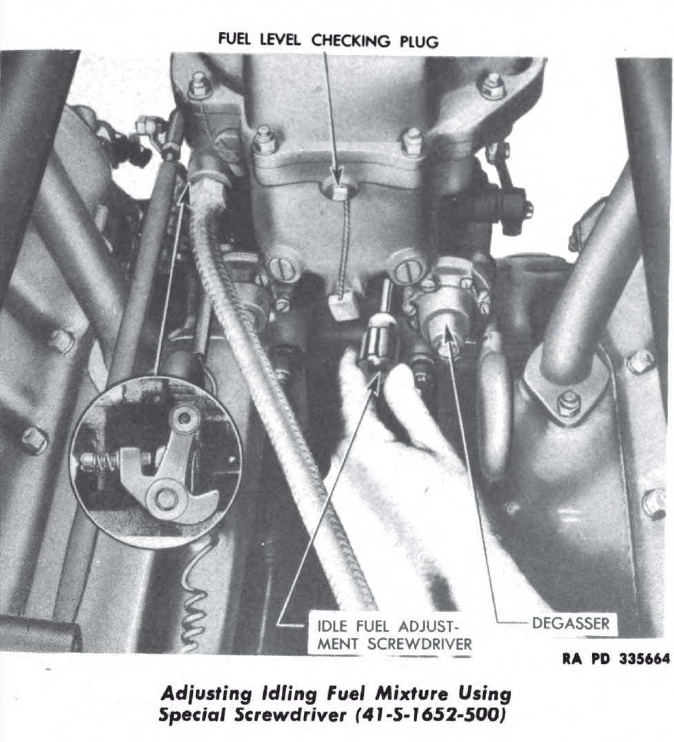
The carburetors were conventional two barrel carbs from Bendix-Stromberg, and I’m sure just about anyone familiar with a 2 barrel carb could rebuild one. The linkage tying the two carbs together was pretty simple and actuated one carb, then the other, making tuning them easier, though, good mixture and fuel distribution to the cylinders had to be pretty uneven.
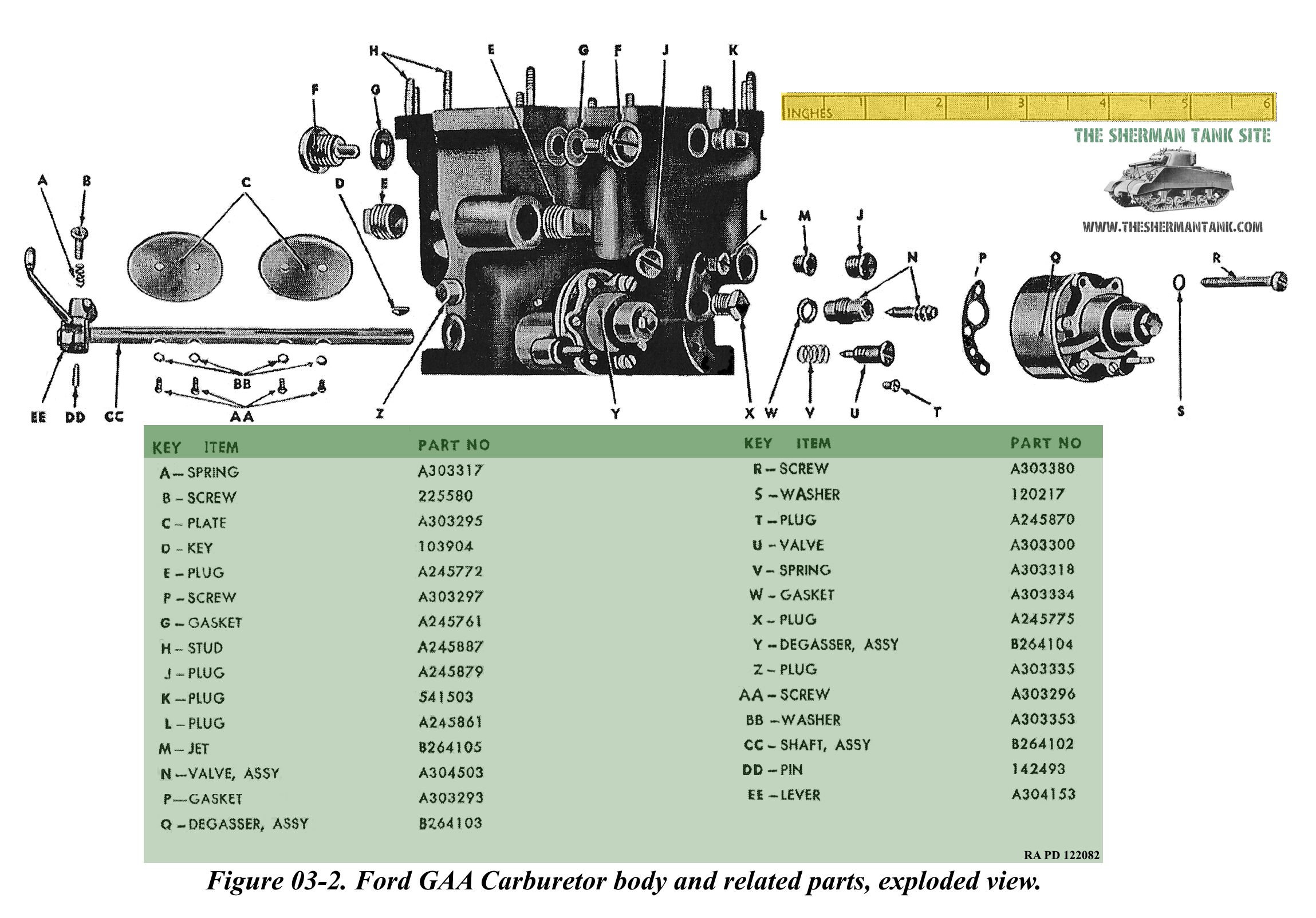

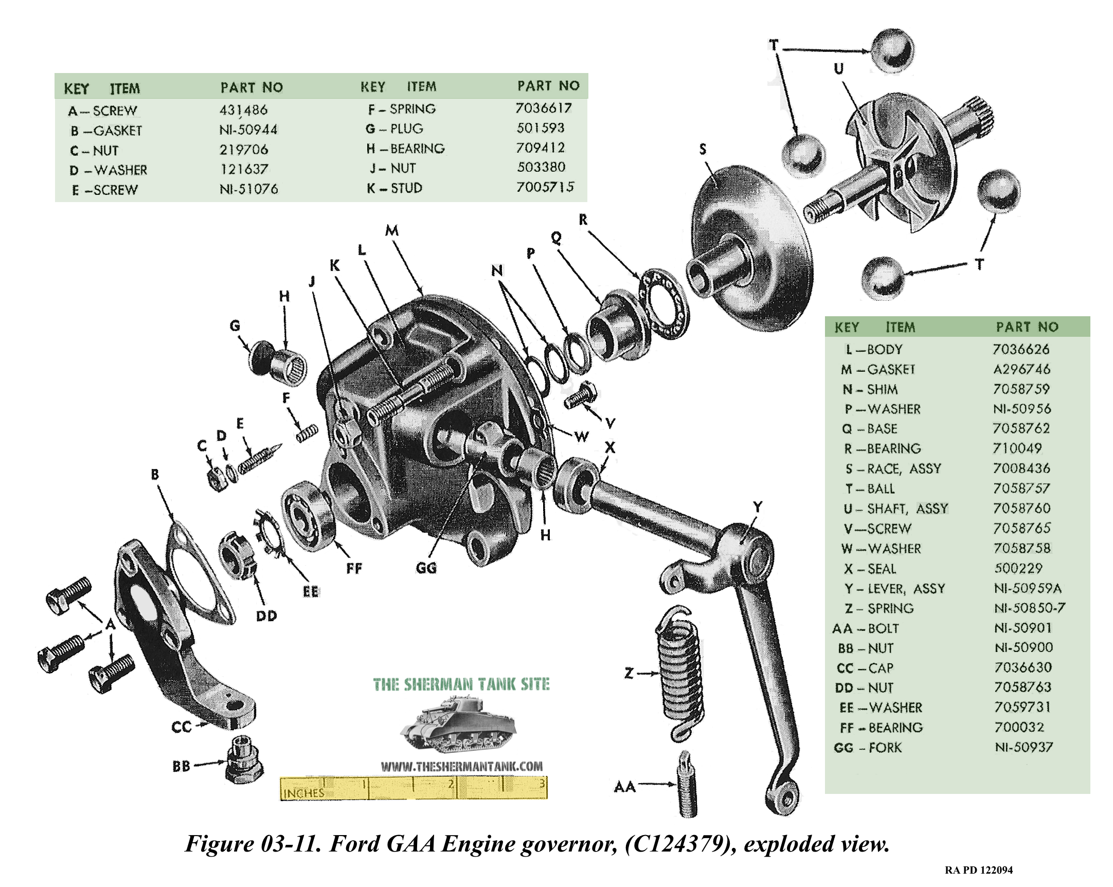
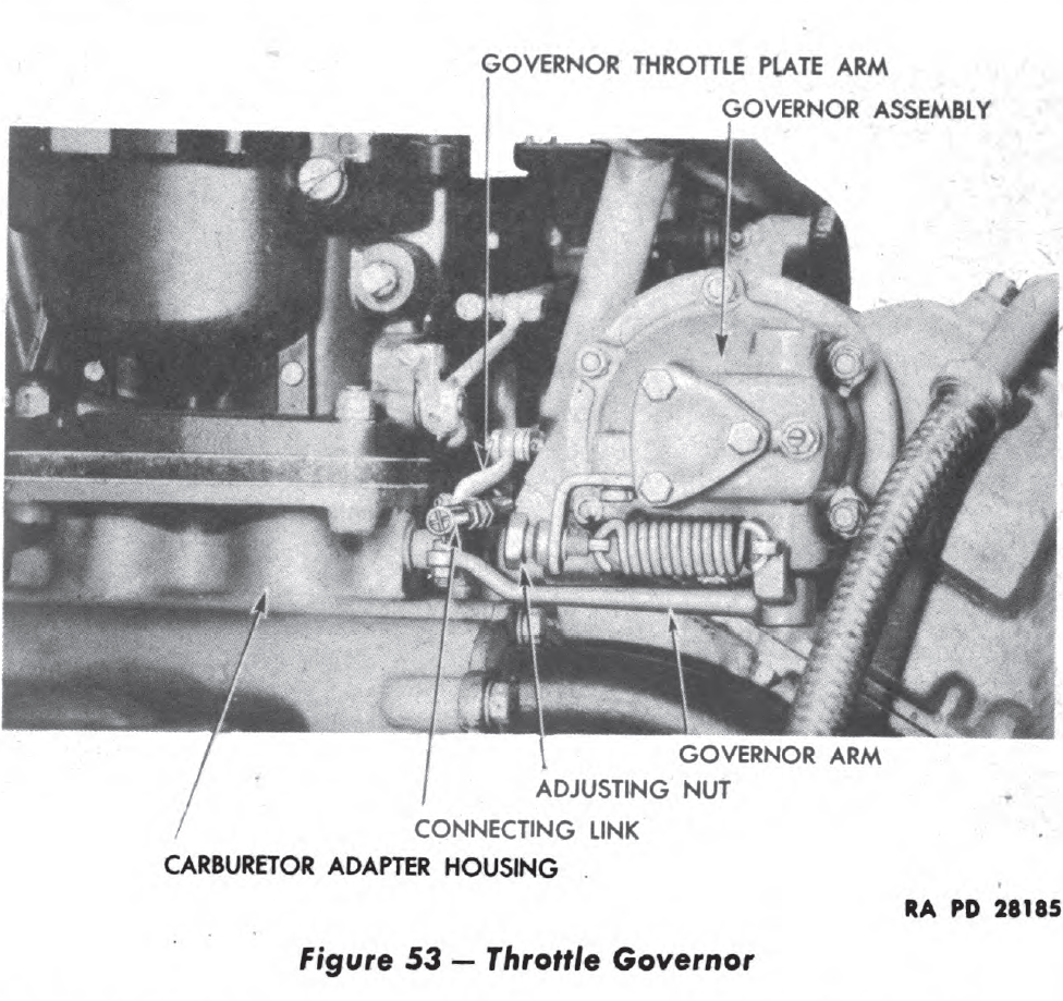
There was an interesting addition to the carbs, they added a carburetor adaptor, with its own set of butterfly valves, these were controlled by the engine’s throttle governor, and as the motor reach max RPM, this butterfly valves in the adapter would actually close to prevent the engine from overspeeding.

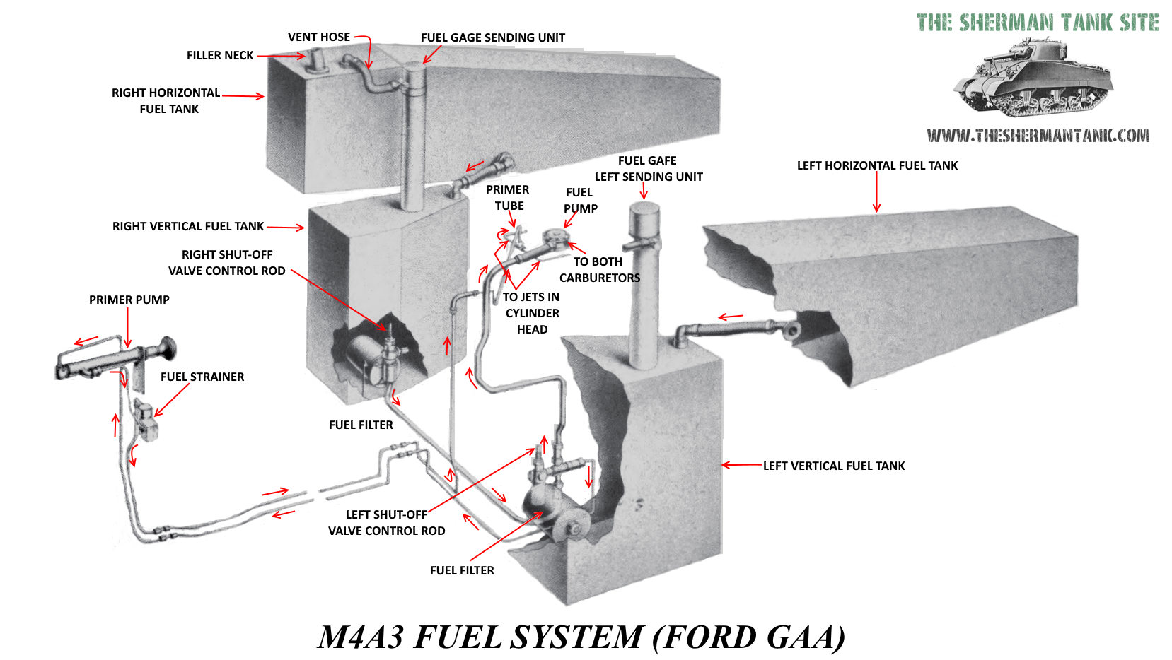
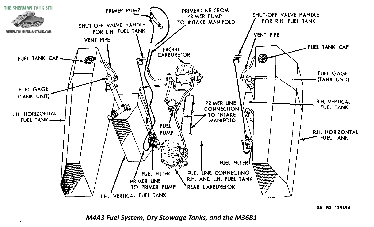

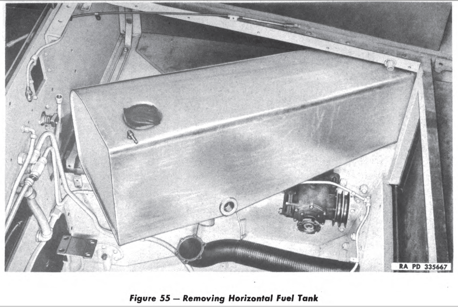
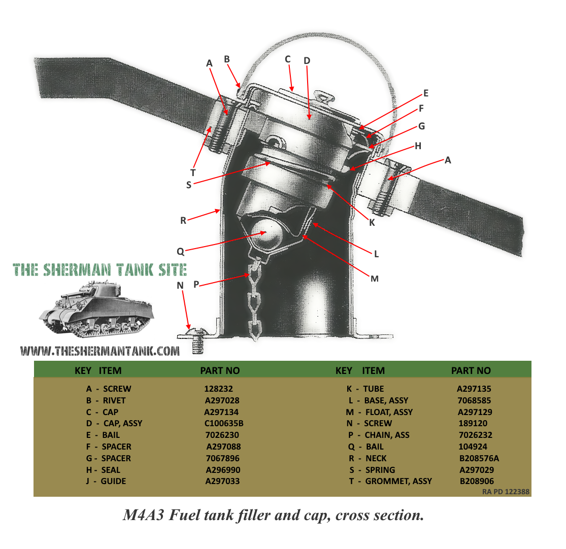
Depending on the model, the M4A3 Sherman had four fuel tanks, in dry storage tanks and the M36B1, they have four tanks, but they work like two big tanks, and have one filler and shut off valve per pair on the back deck. On the wet hulls, the fuel tanks are separated into four individual tanks, each with its own filler and shut off valve. The tanks were steel, and easy to remove, with the motor out, for repair.
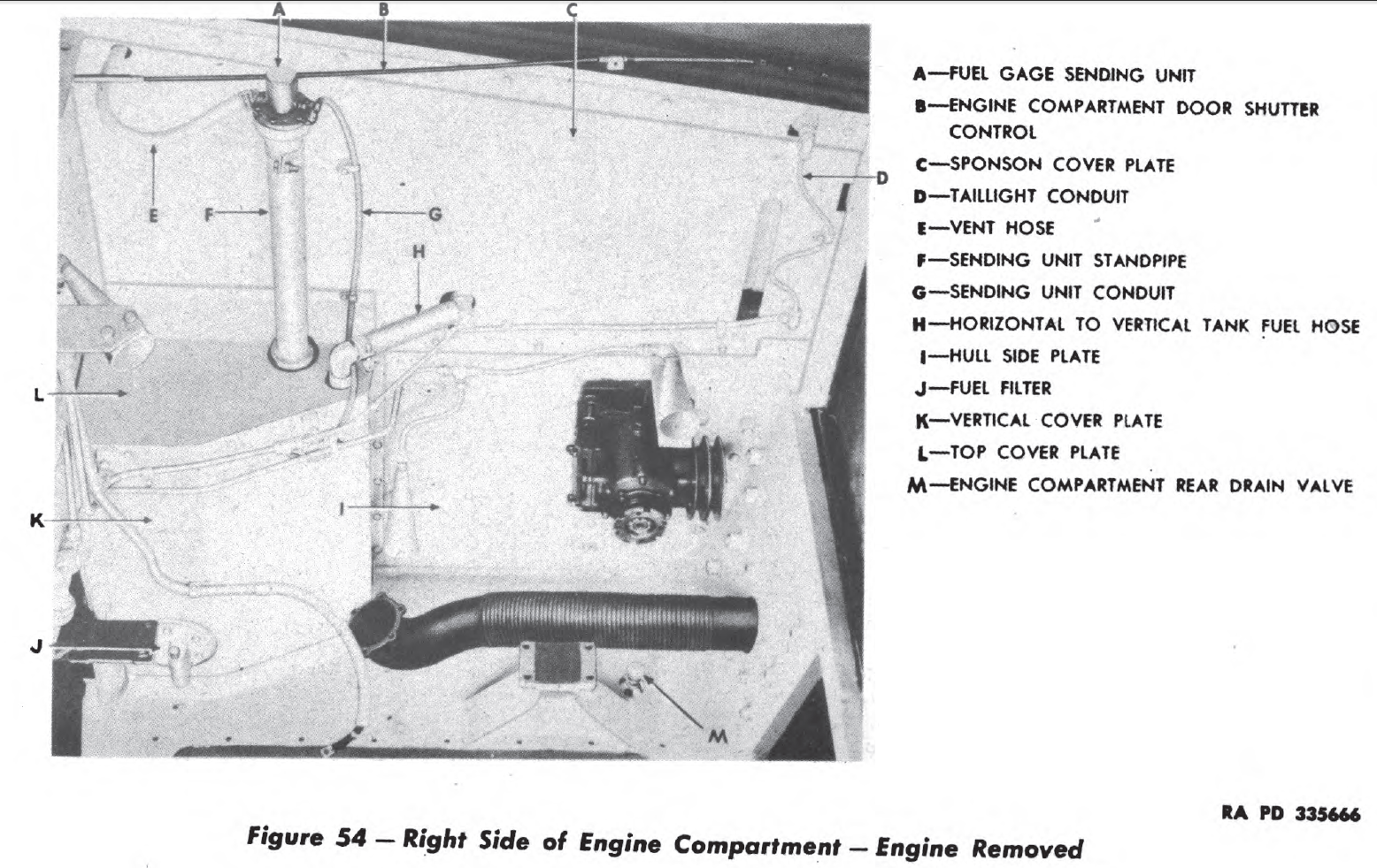
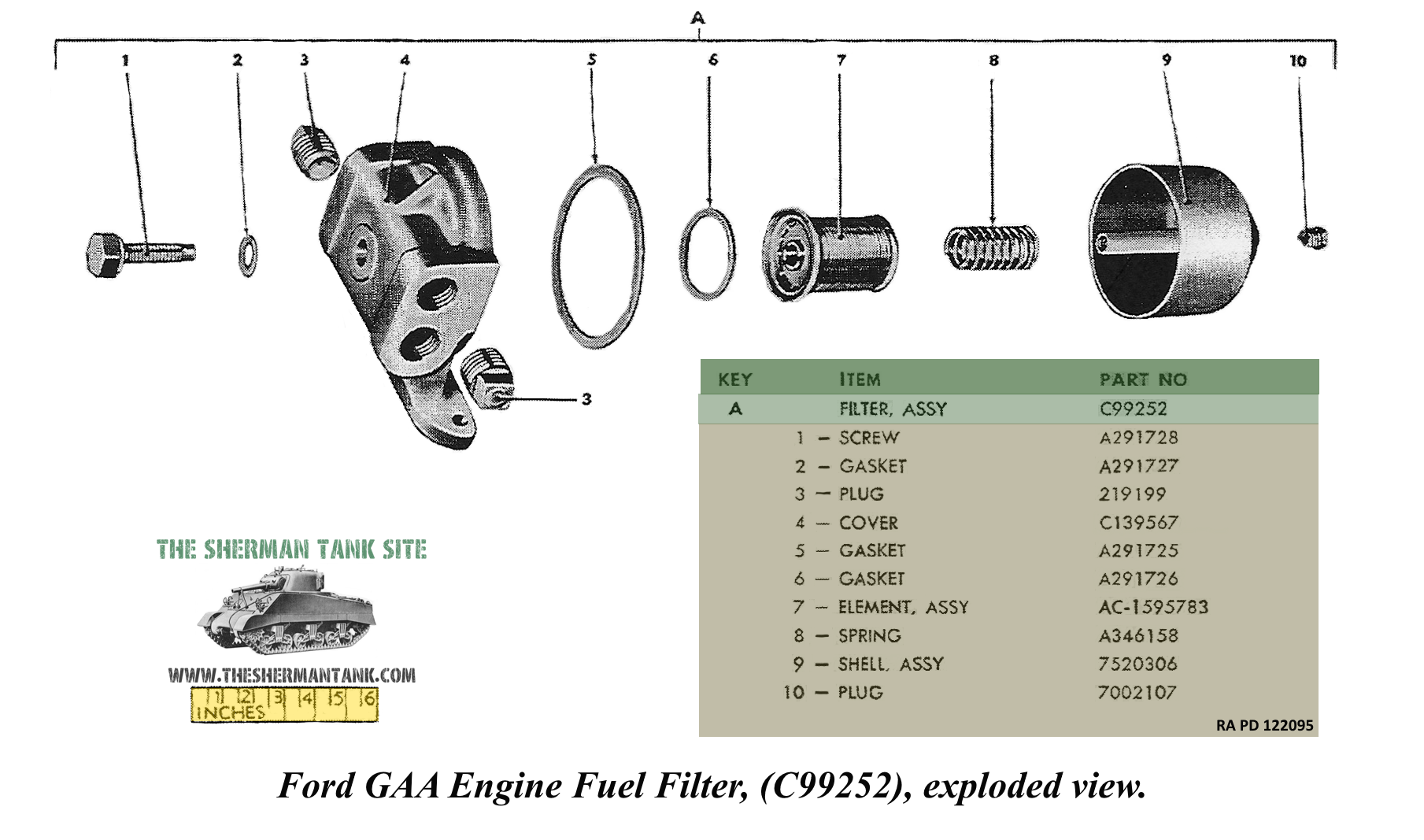
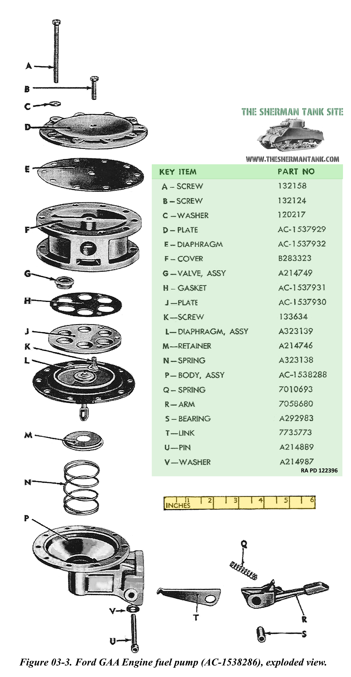
There were filters on each tank on the wet tanks, while the dry tanks had a filter up on top of the engine compartment, just before the fuel pump. The fuel pump was cam driven off a port on the motor, and one version was actually an ACDelco part, and it was a pretty typical diaphragm fuel pump. You typically could find parts from all the major auto manufacturers on the Sherman.

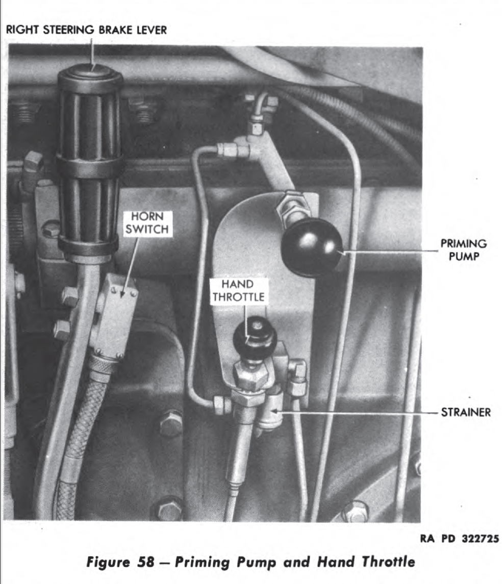
One interesting feature of the fuel system was the hand priming pump in the driver’s position. This was on all models, though it varied from in the dash to mounted in front of the driver for its location. This allowed the driver to pump a little fuel right into the intake to help get the massive beast started.
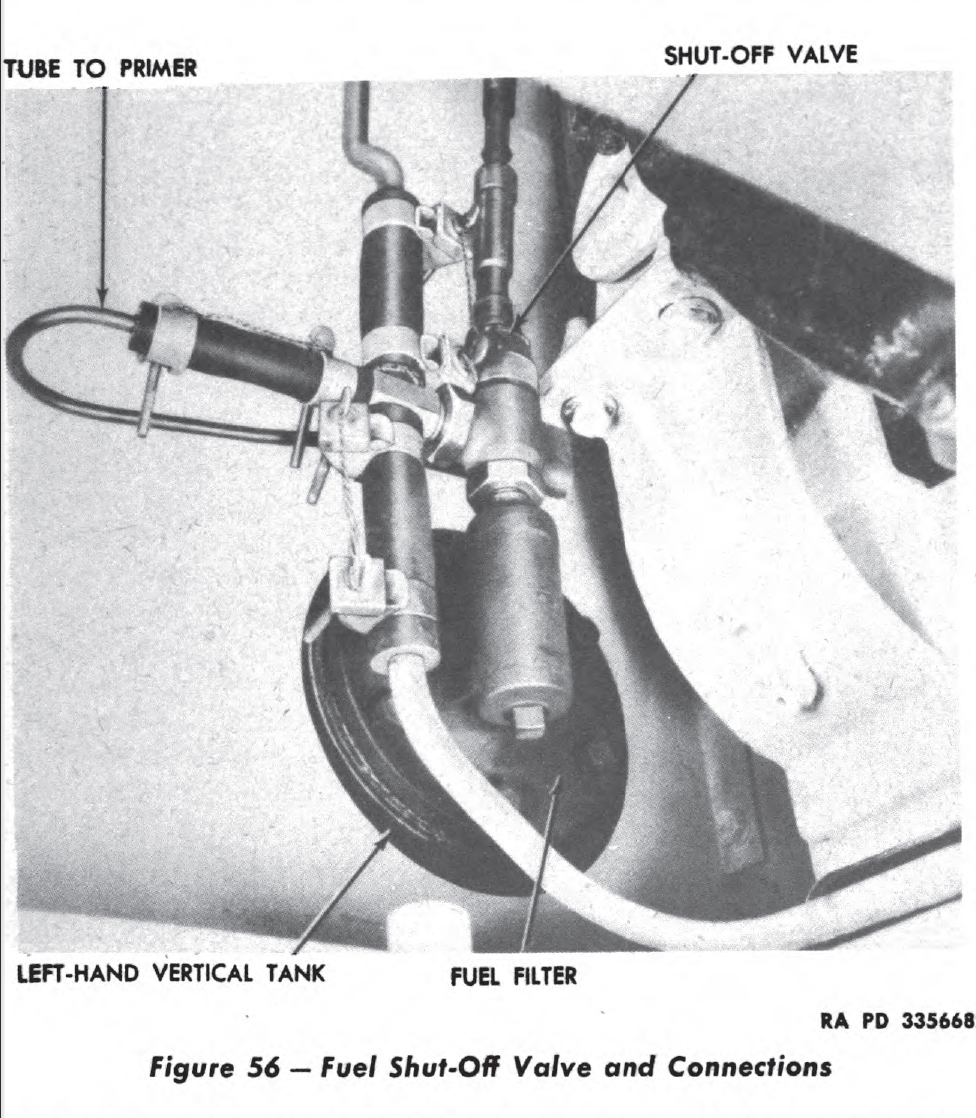
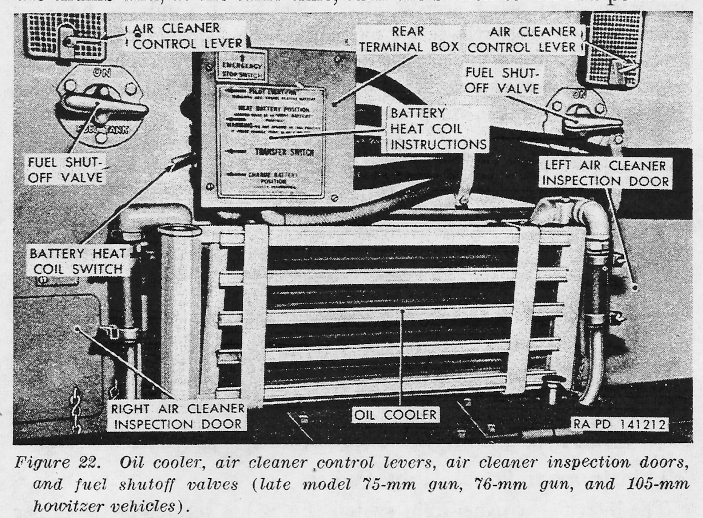
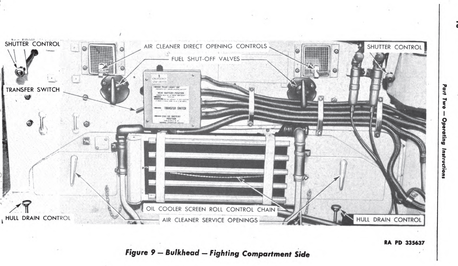
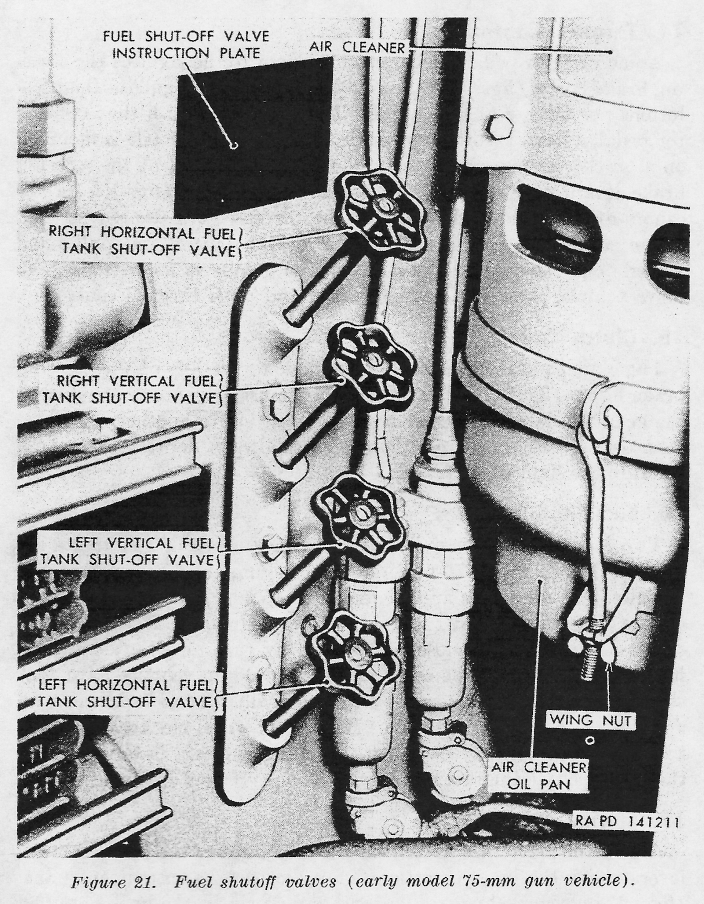
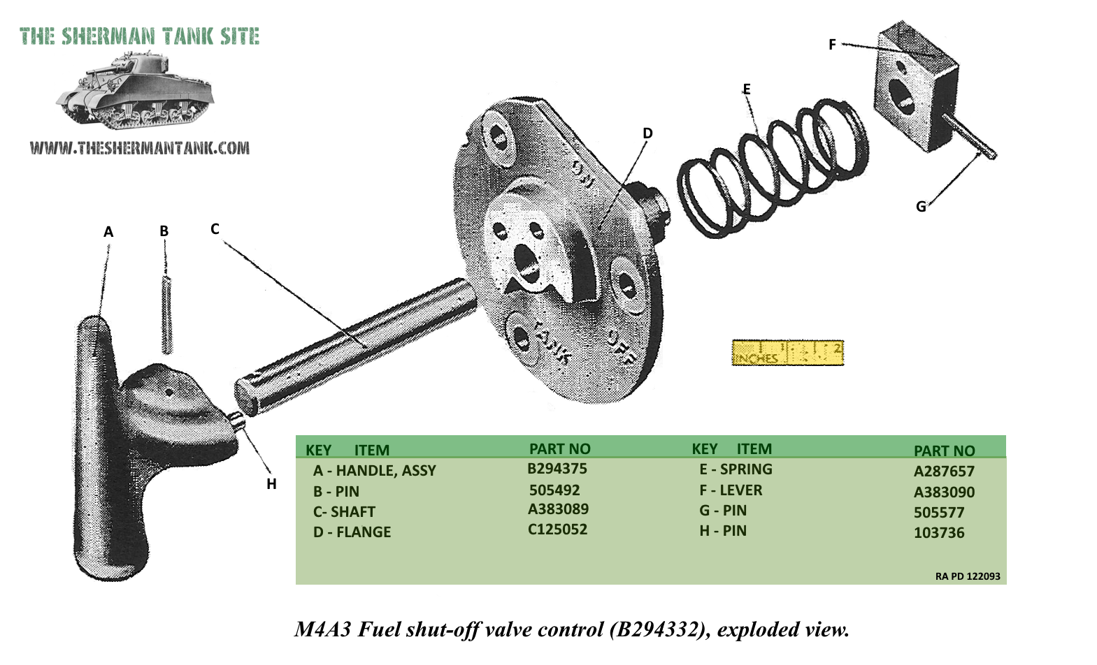
The fuel shutoff valves were operated from inside the tank. They were on the rear firewall and depending on the type of fuel tanks there were two or four of them. If you review the pictures above and below, you will note, the tank layout diagrams show 4 tanks and 4 fuel shut off valves for the wet tanks, and the two tanks made from four tanks, with two shut off valves for the dry tanks, but the firewall photos show only two cut off valve handles on the late firewall, can one handle turn off two tanks?
The fuel tanks were accessed from the rear engine deck, there were five armored covers, or three, two or four for the gas tanks, and one for the gas tank for the auxiliary generator. In the images below you can see the various rear deck configurations.

M4A2, GM 6046 twin Diesel used in the M10, and M4A2 vehicles, fuel system.
Coming soon.
The M4A4, with the A57 multibank motors, fuel system.
Coming Soon.
The M4 and M4A1 R975 radials fuel system.
Coming soon.